GDT Surface Profile is a three-dimensional control ensuring that one or more surfaces are within a specified tolerance. This example demonstrates how to create a GDT Surface Profile item using a surface inspection group that measures a single surface. For example:

To create a GD&T Surface Profile item:
- Open a Geometric group in the inspection sequence..
- Click Geometry tab > GD&T panel > Profile > Surface Profile. The Item Definition dialog is displayed.
- Enter a Name for the measurement.
- Click Next to accept the default Angular tolerance. The Datum Definition dialog is displayed. For example:
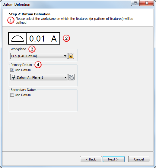
The dialog contains the:
 Instructions, which provide information on how to use the dialog.
 GD&T control frame, which summarizes the GD&T item details. In this example, it shows the Surface Profile symbol, and that the surface has a tolerance of 0.01.
The datum letter is shown against a white background to indicate a GD&T Datum item was selected as the datum. If a sequence item is selected as the datum, the background of the box is patterned.
 Workplane list, which enables you to select the workplane you want to use for the item.
 Datum area, which enables you to select the datums you want to use for the item. Click
  to select an item from the CAD view using the mouse.
 - When you have specified details of the workplane and datums, click Next. The Profile Definition dialog is displayed. For example:
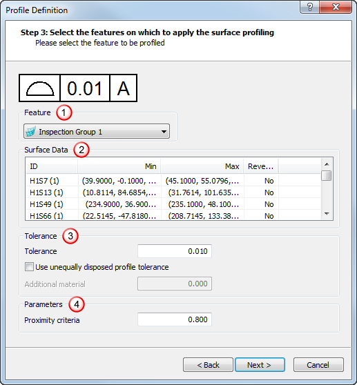
The dialog contains the:
Feature list, where you select the surface inspection group you want to use. Surface data area, which lists information about the surfaces used in the surface inspection group you selected. Tolerance area, where you specify the tolerance values for the surface profile measurement. Parameters area, where you specify the proximity criteria for the surface points. - When you have specified details of the feature and tolerances you want to use, click Next. The Result Preview dialog is displayed. For example:
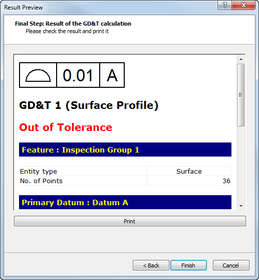
Scroll down to display information.
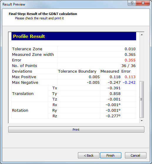
- To print the information, click Print.
- Click Finish to add the GD&T item to the inspection sequence.