Planes are usually the first tool we use for viewing results in our models. With planes you can view velocity or pressure contours or velocity vectors on a slice through the flow. They are convenient, and easy to understand.
This video and tutorial describe how to visualize results with Planes. As you watch the video, please follow along in Flow Design. Feel free to pause the video at any time to practice the skill, or simply watch it all the way through and practice with the steps in the tutorial.
Tutorial: Use planes to view Results
If you haven't already, start Flow Design and open one of the sample models. We used the building model in the tutorial, but any of the examples will do.
|
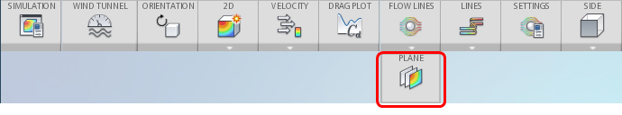
Step 1 If the plane does not appear because flow lines or iso surfaces are shown, expand the icon and select Plane:
|
|
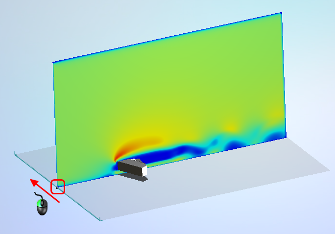
Step 2 Move the plane by dragging the drag handle to a new position:
|
|
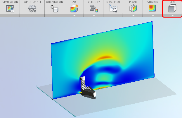
Step 3 Reorient the plane by selecting one of the pre-defined orientations from the ribbon: Side
|
|
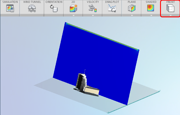
Step 4 Reorient the plane to the Front.
Note: Front works well for 3D simulations, but is not recommended for 2D simulations.
|
|
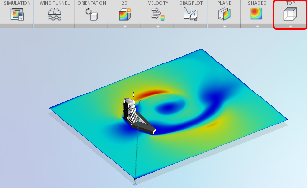
Step 5 Reorient the plane to the Top.
|
|
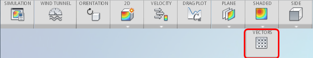
Step 6 Display vectors by expanding the menu under Shaded, and selecting Vectors:
This provides a better view of the flow direction and trends. |
|
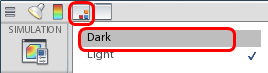
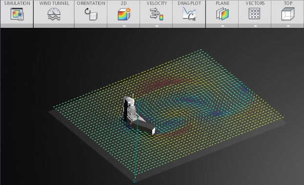
Step 7 Get a better view of the vectors by changing the background to Dark from the toolbar:
|
|
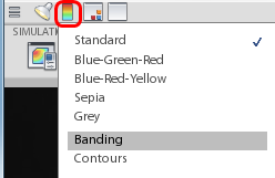
Step 8 Control the appearance of the plane by selecting from the options on the Color Scheme tool in the toolbar:
|
Next Steps
To learn about viewing results with flow lines, watch the next video and tutorial.
Additional Information
For more information about viewing results with planes, you can review additional information here.
To learn more about the meaning of flow results, check out the Understanding Results topics.