Legacy tutorial posted on the old Alias Design Community site on October 14, 2008, by Joshua Maruska.
Natural Surfacing Part II
In the first part of this surfacing demo, I showed techniques for setting-up surfaces with some forethought toward CV placement, creating a work environment suitable for Four-way Symmetrical modeling, the use of reference surfaces to guide the sculpting of a form and a general approach to moving CV's to refine a shape or to make drastic changes.
Next we will continue with the development of this sports watch concept by adding detail and further refining the form.
Helical Strap
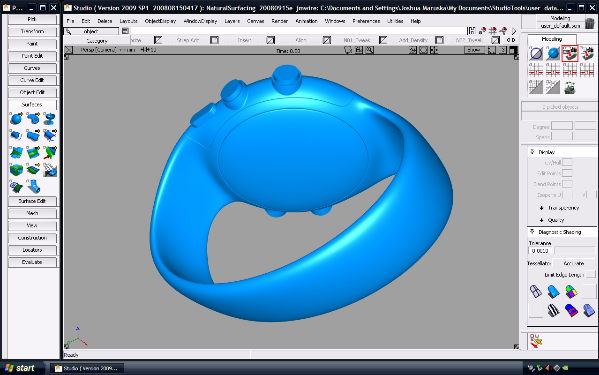
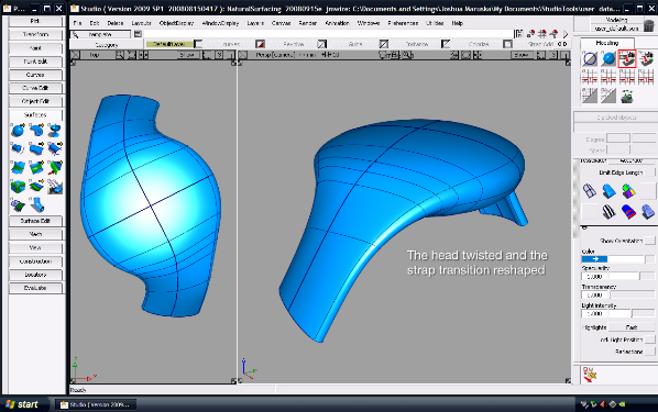
At the end of the first part, we made a dramatic change to the design of this product by going from a symmetrical design to one that is twisted in form.
The symmetrical version was modeled with a head piece and two strap extensions that splayed outward in a linear fashion at 30 degrees. These linear extensions are the right way to model a strap that will be manufactured, but they don't help the designer visualize how the product will look in context - on the wrist. Here are the steps I used to create a version of the design with a formed strap.
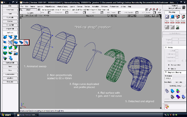
The strap needs to be a helix in shape for it to fit properly on the wrist. I've made these twisted straps a variety of ways and this is the best way I've found to make a comfortable one that's a proper spiral with parallel interior walls.
I used the animated sweep tool to create a helix. The helix is the same width as the diameter of the head from outer tip to outer tip and is 60 mm in diameter. However, for a watch to look natural, it should be built around an elliptical "wrist".
I'll go through the above steps individually...
Curve Set-up
The basic idea behind using the animated sweep tool is this: animate a curve through 3D space using the standard key framing tools, then the Animated sweep tool steps through the animation, frame-by-frame skinning the curve as it translates. It's like using the skin tool, but Alias does all the work.
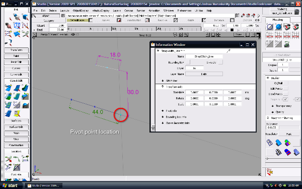
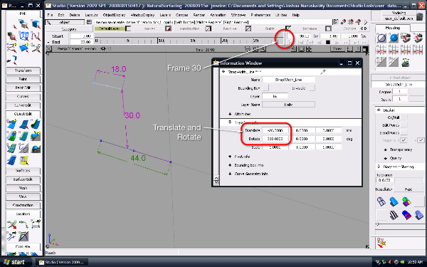
To start, I created a line that is the width of the strap (18 mm). I also created a reference line that is the width of the watch head (44 mm) it is 30 mm below the first line - which is half the diameter of the helix we'll be creating.
Then, set your pivot location for the first line to the end of the second. This will ensure that when we animate our first line, it will circumscribe a 60 mm circle as it move along the X axis creating the helix.
When the line is created and it's pivot point set choose Animation > Set Keyframe to keyframe the line's transform values.
Animate the Line
There are a few things that happen here. First, I set the time slider to frame 30. This will give us 30 steps to our animation, which will result in 30 profile lines through which the animated sweep will sweep through.
Second, I moved the strap width line over by 26 mm (44 mm minus 18 mm).
Then, in the transform window, I set the strap width line's X rotation value to 360 degrees. In the view port window, you won't see a change in rotation, but to the animation, there is a big difference between 0 degrees and 360 degrees.
Set a keyframe at frame 30 to keyframe the line's transform values there.
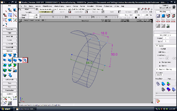
Animated Sweep
The Animated Sweep tool is pretty easy to use. Just pick a curve that has been animated and then pick the tool.
If you just end-up with a bunch of lines and no surface, open-up the options box for the Animated Sweep tool and select 'connect snapshots'.
You should now have a surface with 30 spans that twists like a helix.
Make it Elliptical
The strap we are building needs to be elliptical in shape - like your wrist - but the animated sweep we made was round. Scaling the sweep by 2/3 in the vertical axis. It should be 60 mm by 40 mm now.
Our next step involves making a rail surface based on this guide. You could have made the 'strap width line" any width and ended-up with enough information to proceed to the next step - but using a line that is dimensionally accurate allows you to make a visual inspection of the way things are headed before you get there. I like to work from 'general to specific' but efficiently as well.

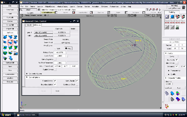
Duplicate Curve and Rail
Here, I increased the patch precision on the animated sweep by 1 to get a center-line. Duplicate it to form the rail. We will sweep a generation curve about it to make the strap.
Next I position a duplicate of the end profile of the Master Surface and use the Birail tool to create a single generation curve/single rail surface.
Order counts: so why not just skip the animated sweep of the simple and just animate the generation curve? Because of the non-proportionate scale we needed to do to create the elliptical shape. If we had swept the profile first, and then scaled, the strap would have been thinner in profile in the Z axis when we made the elliptical shape. This way, we have an elliptical helix in shape, but a constant material thickness in section.
Since this whole animated sweep thing is a lot of steps to follow along with, I've included a wire file that shows these last few steps.
Putting it Together
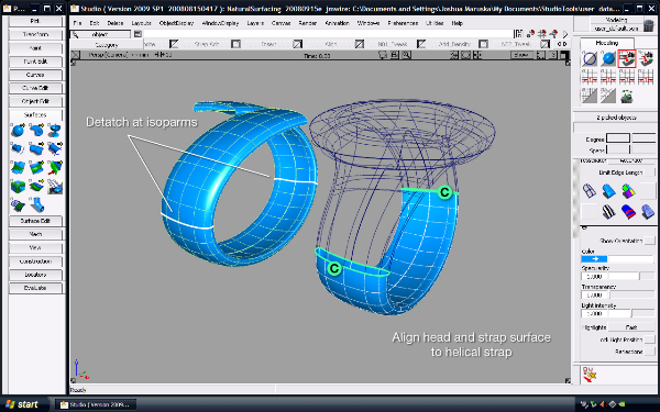
The helix was made using one full revolution which is more than we need. The head and strap transition 'Master' surface actually complete the majority of the upper form, so we really only need the lower half of the helix.
I used the detach tool to break apart the helix and discard the bits I don't need. I find this works better than trimming because the resultant edge is pure and natural, where as a trimmed edge may have some garbage in it. Try it both ways to see the difference.
Once the helix is cut down, we can align the Master Surface to the helical strap and we are back in business.
I should also mention here that The Master Surface here is a bit different than one we had in the previous section. In Part One, I introduced a Quad Symmetry workflow in which we worked on only a quarter of the product. With this new twisted design, having four sections to the model is not necessary and a bit impractical so there are only two symmetrical halves - no longer left/right and near/far. The left/right parts are now one. This did require a rebuild of the model thus far. I could have used the Attach Tool to join, but in this case starting over was faster than trying to sort through the extra CV's Attach can introduce. I used all the same steps from Part I to reach this revised model.
Back to Tweaking
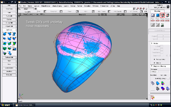
Tweaking CV's is not unlike the "Wash, Rinse, Repeat" instructions on a shampoo bottle. The more you do it, the cleaner things get. After another round of tweaking CV's, we're ready to cut-in the lens crystal and see where we're at.
I usually find that I can cut-in 'the next major feature' beyond the Master Surface and get a good feel as to how close I am to being done. This is much like the projected curves and deviation check we did earlier, but with higher fidelity. It'll only takes a few minutes in this case.
Check your Work
I'm always going back and evaluating the seams of my model. Since the next step involves a trim operation I want to make sure we're all properly aligned before I go there. Often times, things like rounds and filets will fail because one surface is slightly out of tangent. It may not show-up in your shaded view, but most surfacing tools aren't that forgiving.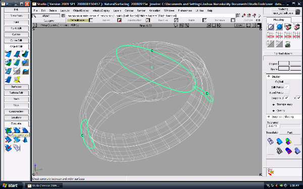
Lens Cut-in
Here, I've trimmed the lens into the Master form. The lens itself is made from the original revolve that has been trimmed to size (it's no longer shaded pink). There is a small 0.6 mm gasket between the lens and body. The rest of the form is made only from the Master Surface and helical strap surfaces.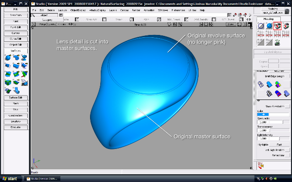
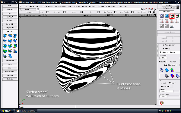
Surface Evaluation
Depending on your license of Alias Studio, you'll have different diagnostic shaders to evaluate your surfaces with. The zebra stripe is pretty common and I use it quite a bit. I find that I have to use a fairly high tolerance setting on the tessellation to get pleasing visual results though. This session is set to "0.001" tolerance and the "accurate" tessellator.
I'm looking for obvious discontinuities in the surface. The zebra stripes should flow fluidly from one surface to the next. If the stripes stop abruptly or change direction unexpectedly, you probably have a continuity issue with your surfaces.
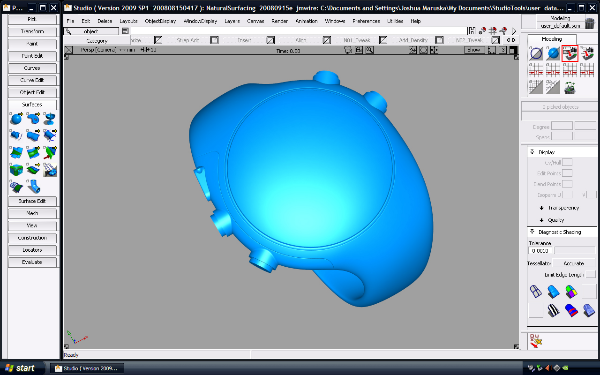
Buttons Added
I've taken the model to the next level. All this detail uses standard patch modeling techniques. The main buttons are revolves and the illumination button at the top of the shoulder is a drafted surface that's been capped with a plane and filleted.
As a side note, I do tend to 'dress' all my edges. Even sharp-cornered parting lines have a tiny 0.1-0.2 mm radius on them. It helps to delineate different parts when it comes to rendering them. If the bezel around the left-side buttons weren't dressed, it wouldn't show in this shaded view. The parting edge would be colinear with its adjacent part and disappear.
Buttons Bottom View
Not much more to see here. The battery door has been parted out. It too is cut from the revolve rather than the Master Surface, but the continuity from one to the next is near seamless.
In this segment of the series we've looked at how to use the Animated Sweep tool to create complex twisting geometry, use the align tool to transform geometry from one 'pose' to another and how surfaces that were modeled with Natural Surfacing techniques can merge with other surfaces to complete a product.
Next we will continue to detail the watch using other ways of pulling forms from CV's and end=up with a completed design.