Use Evaluate > Continuity > Surface Continuity to check the deviation and continuity along shared edges of surfaces.
Use Locators > Deviation > Angular Deviation to check for tangent continuity (G1) between surfaces, regardless of whether or not they have achieved positional continuity (G0).
Check the continuity between surfaces
- Pick the surfaces you want to check.
- Choose Evaluate > Continuity > Surface Continuity
 .
. The tool displays symbols along the shared edges representing the continuity and deviation at each sampling point.
Tip:To get a complete review of the deviation and continuity set all options on: Locator Persistence, Show Max. Labels, Check interior, Show Edge Labels, and Show Comb.
Note:The calculation can take a long time for very complex models. To cancel the check, press
 .
. - Do any of the following:
- Click an edge to add it to or remove it from the check. Hold
 and click a surface to add it or remove it.
 - Drag the
 on empty space to change the scale of any active deviation comb plots.
 - Drag the
 on empty space to change the sampling density.
 - -click an edge to switch it between deviation comb and symbol display.
- Drag the
 along an edge to show detailed numeric information on the points under the mouse pointer.
 - Open the prompt-line history window to see any messages the tool printed about continuity and deviation between the surfaces.
- Click an edge to add it to or remove it from the check. Hold
How do I read the symbolic display?
| Line style | Meaning |
|---|---|
| Pale green, dotted. | Edge with no adjacent surface, or an adjacent surface that is not selected. Hold |
| Bright green | Selected isoparametric curve with achieved continuity. |
| Dark green | Isoparametric curve with achieved continuity. |
| Yellow | Selected isoparametric curve with continuity break. |
| Red | Isoparametric curve with continuity break. |
| Symbol | Meaning |
|---|---|
| Cross | Requested continuity achieved. |
| T | Tangent/normal break. |
| C | Curvature break. |
| O | Gap in the common edge (think of the “O” as a hole). |
| Blue symbol | Minimum measured deviation. (Not shown if minimum deviation is 0.) |
| Red symbol | Maximum measured deviation. |
These colors may be different if you have changed the interface color preferences.
Check tangent continuity (G1) between surfaces that may not have positional continuity (G0)
- Choose Locators > Deviation > Angular Deviation.
- Select the boundaries between two sets of surfaces by clicking them in turn (the pick chooser may appear), or box-selecting them. All the surfaces in a set must be connected. Additionally, if they are tangent continuous, they can be selected all at once by turning on Chain Select in the control window. Note: You can select surface edges, trim edges, and surface curves.
- Click the Accept button that appears in the view window.
A G1 locator is displayed, showing a green T if tangent continuity is achieved, or a yellow T if it is not. By default, the maximum angular deviation between the surfaces is displayed, as well as edge labels. You also have the option of displaying a comb showing the magnitude of tangency breaks along the boundary.
- Click Next in the control window to check tangent continuity between another set of surfaces.
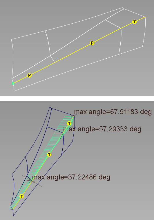
An example
Below are two sets of surfaces. The Surface Continuity tool shows that the longer surface fails to achieve positional continuity with its neighbors (top). The Angular Deviation tool can still be used to check tangent continuity and show angular deviation between those surfaces (bottom).
What if...?
These troubleshooting tips apply to the Locators > Deviation > Angular Deviation tool as well.
- I want the comb plots on all the surfaces to use the same scale
-
- Choose Evaluate > Continuity > Surface Continuity

- Turn on Show Combs, and turn off Auto Scale.
- Enter the scale factors for Positional, Tangent, and Curvature deviation combs respectively in the three Scale fields.
- Choose Evaluate > Continuity > Surface Continuity
- I want to change the tolerances?
-
Choose Preferences > Construction Options
 and open the Tolerances and Continuity sections.
 - The calculation takes too long?
-
Choose Evaluate > Continuity > Surface Continuity
and increase the Distance Between Checks setting to make the tool calculate fewer sample points.