|
In this lesson, you set up the Alias environment and create a file that is ready for you to start modeling.
Objectives
- Set up Alias preferences.
- Learn about the ViewCube and NavBar.
- Create a file.
- Import and place reference sketch files.
- Adjust the sketch layer opacities.
- Save a file.
Prerequisites
- Alias is installed.
- The tutorials reference image files have been downloaded from the Alias wiki.
- Alias is open in a blank document state.
- You have watched the Essential Skills videos.
 Watch video
Set up your preferences
The Alias interface is flexible and customizable. You can set up the interface and input options to your preferences. For this set of tutorials, use the options set in this section. These settings are used in the videos and screen images.
Set the position of the Palette and Shelf on your screen
This set up is optional, but highly recommended if you are unfamiliar with the Alias interface, or will be following the video versions of these tutorials as well.
- Open the options window for the menu item Preferences
 InterfacePalette/Shelves LayoutPalette/Shelves Layout by clicking the
  box icon to the right of the menu item name. The Palette/Shelves Layout options window opens.
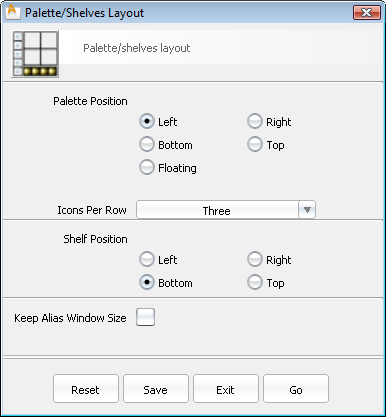
- Under Palette Position, select Left.
- Under Shelf Position, select Bottom.
- Click the Go button.
Your interface changes take place immediately, and are stored for the next time you launch Alias.
Enable face selection
- Open the options window for the menu item PreferencesSelection Options by clicking its . The Selection Options window opens.
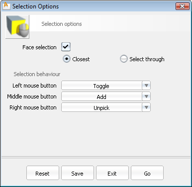
- Check Face Selection on. This will allow interactive picking of surfaces in the scene by clicking anywhere inside their wireframes, where an interior face region is defined. Note: Without Face Selection on, all surfaces must be picked by clicking on their visible wireframes.
- Chose Closest as the face selection style. Note: Closest face selection sets the priority for visually overlapping surfaces. The surface closest to the current view will be picked, even in wireframe view, if two surfaces are visible in the same place on the screen.
Set the number of Undos and the memory usage based on your computer system memory
- Choose PreferencesGeneral Preferences to open the General Preferences options window.
- Click the Miscellaneous section on the left and set the Maximum Undos to 50 and the Maximum memory to 500 megabytes.
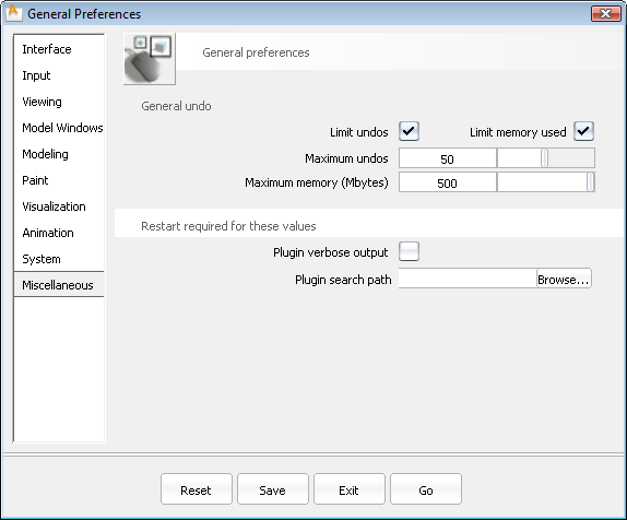
- Click the Go button.
Interface Essentials
If you have not already viewed the Essentials Skills videos, do so now (in Alias, select HelpLearning Movies).
Beyond the interface tools shown in these videos, these are two valuable tools to increase your comfort and speed when working in Alias:
- Marking menus
- ViewCube and NavBar
Marking menus
Marking menus are a fast way to access frequently used tools and commands directly within any view or window.
Hold down the  and
and  keys and press either the
 ![]() ,
, ![]() , or
, or ![]() mouse buttons to access a floating, radial menu of commands around your mouse cursor. This menu persists until you release the mouse button.
mouse buttons to access a floating, radial menu of commands around your mouse cursor. This menu persists until you release the mouse button.
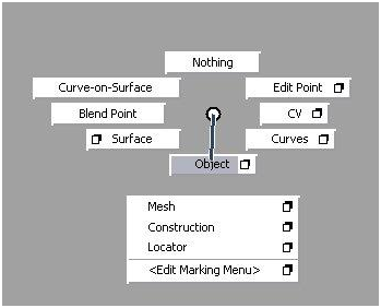
You select the tools and menu items by releasing the mouse button over them.
Access the options window for a tool by releasing the mouse button over the ![]() located to the right of the tool or menu name.
located to the right of the tool or menu name.
and and holding the appropriate mouse button) is enough to activate the tool. This technique is much faster than accessing frequently used tools by finding and clicking on their icon or menu item. ViewCube and NavBar
The ViewCube and NavBar are familiar elements in many Autodesk applications. They allow quick navigation around the scene.
The ViewCube is visible at all times, but is dimmed when the mouse is not near it. The NavBar only appears when you press the  and (Windows) or
  and (Mac) keys.
For information on using the ViewCube and NavBar, see the Alias Help.
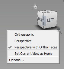
- Click the context menu arrow just below and to the right of the ViewCube and select Perspective with Ortho Faces. It will be checked when active.
This setting displays the view with natural perspective when you click any corner or edge of the ViewCube or tumble around the model, but reverts to traditional orthographic views when you click a face of the ViewCube.
You can toggle the ViewCube on or off in the Preferences General Preferences ![]() option box (Viewing section).
option box (Viewing section).
Set up a new file
Now that you have set up general application preferences and viewing conventions, you can create a file with appropriate settings for the size and eventual output of the model.
Create a file
- Choose the menu item FileNew
 to start a new, empty document, and confirm the deletion of all objects, shaders, views, and actions.
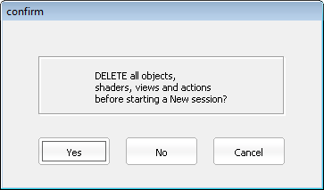
Define Construction Options for the file
Construction Options ensure that modeling is done with the tolerances and units that other applications expect when refining the engineering of our design. These settings do not generally constrain the creative process, but using a preset now allows for later modification and expansion in Autodesk Inventor.
- Choose PreferencesConstruction Options
 .
. - Under Construction Presets, click Inventor to set the units to millimeters and set tolerances to allow easy interoperability with Autodesk Inventor.
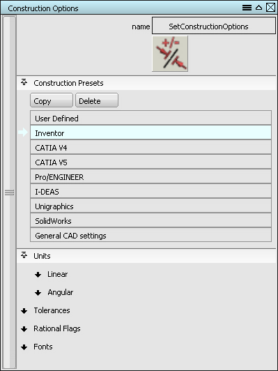
- Close the Construction Options window.
Change the grid layout
The finished model for this tutorial is approximately 400 mm in the longest dimension. This is much smaller than the default grid layout in Alias.
- In the Palette window, click the Construction tab and then double-click the Grid Preset tool to open its options. Note: In these tutorials, this tool location and its options can be written as ConstructionGrid Preset
 . This is the menu flow visible by
  -clicking on the Construction tab in the Palette.
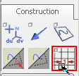
The Preset Grid Options window opens.
- Set the Grid Spacing to 10 mm and the Perspective Grid Extent to 400 mm. All other settings can remain at their defaults.
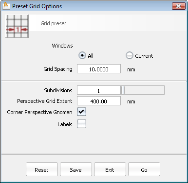
- Click the Go button to commit these settings and change the grids in all views.
Import reference images
To assist the modeling process, a sketch is often used as a reference. The sketches for this tutorial are provided at the end of this page. You will import Top, Left, and Back view sketches into your scene.
Save the reference images VacuumTop.jpg, VacuumLeft.jpg, and VacuumBack.jpg to your Alias demo project pix folder, typically found at (Win)..\Users\<username>\Documents\Autodesk\Alias\user_data\demo\pix or (Mac) /Users/<username>/Documents/Autodesk/Alias/user_data/demo/pix
Create a canvas plane for the top view image
Alias Surface users skip this section.
- Choose LayoutsAll WindowsAll Windows
 to show the Left, Top, Back, and Perspective views, if they are not already visible.
 - Click in the Top view to make it active (a thin, white highlight appears around the edges).
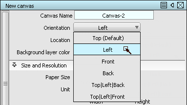
- Choose CanvasNew Canvas
 .
. The New Canvas options window opens.
- Set the following options:
Paper Size to Custom
Unit to Millimeters
Pixels Width to 1680 and Height to 640 to match the resolution of the image you are importing.
mm Width to 420 and Height to 160 to match the physical size of the new object.
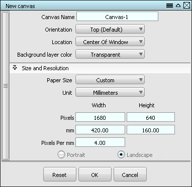
- Click OK. A new canvas is created in the Top view.
Add the top view image to the canvas
- Alias Surface users only:
- Choose LayoutsAll WindowsAll Windows to show the Left, Top, Back, and Perspective views, if they are not already visible.
- From the Palette Pick tab, choose the Pick Object tool.
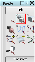
- Pick the canvas plane for the Top view.
- Choose Layouts
- Select FileImportCanvas Image
 .
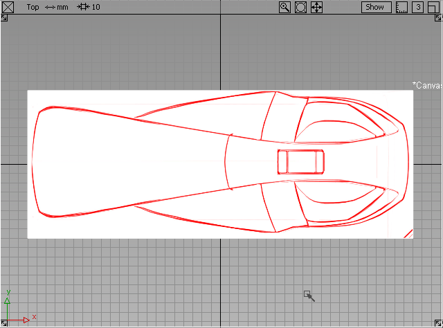
. - Browse to the VacuumTop.jpg file in the pix folder. The image is centered in your Top view canvas.
Create a canvas plane and add the left view image
- Alias Surface users only:
- From the Palette Pick tab, choose the Pick Nothing
 tool.
tool. - Pick the canvas plane for the Left view.
- Skip to step #4.
- From the Palette Pick tab, choose the Pick Nothing
- Click in the Left view to make it active.
- Select CanvasNew Canvas and set the following options: Set the Orientation to the Left view.
Paper Size to Custom
Unit to Millimeters
Pixels Width to 1680 and Height to 640 to match the resolution of the image you are importing.
mm Width to 420 and Height to 160 to match the physical size of the new object.
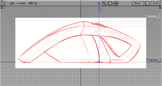
- Select FileImportCanvas Image and choose VacuumLeft.jpg.
- Import the VacuumLeft.jpg file using the same settings as the Top.
Create a canvas plane and add the back view image
- Alias Surface users only:
- From the Palette Pick tab, choose the Pick Nothing tool.
- Pick the canvas plane for the Back view.
- Skip to step #3.
- From the Palette Pick tab, choose the Pick Nothing
- Finally, create a third canvas for the Back view following the steps above.
Set Pixels Width to 640 and Height to 640.
Setmm Width to 160 and Height to 160.
- Import the VacuumBack.jpg file to this canvas.
Move the canvases so that vacuum design rests on the XY plane
In the Left and Back views, notice that the canvas is centered on the origin as in the Top view. The vacuum design should be resting on the XY plane in the positive Z direction.
- From the Palette Pick tab, choose the Pick Object tool.
- Pick the canvas plane for the Left view.
- Next, pick the canvas plane for the Back view.
- From the Palette Transform tab, choose the Move tool.
- In the Left viewport, press the and drag to move both canvases along the Z axis until the bottom of the sketch is aligned with the darker "origin" line.
- Once the canvases are positioned, press the
 and keys, and click with the
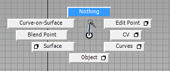
  to bring up the Pick marking menu.
 - While holding down the mouse button and marking menu keyboard shortcut, drag upward to choose (Pick) Nothing, which deselects all objects.
 Note: Later in these tutorials, the command (Pick) Nothing (and other common marking menu items) will simply be noted. Using the marking menu to access the command is the easiest and fastest method.
Set image canvas display preferences
To make it easier to see the geometry and other elements in the scene, dim the Canvases and place them in a new layer that prevents picking the canvases during modeling.
- To create a layer in the scene, choose LayersNew
 .
. A new layer appears in the Layer Bar below the prompt line.
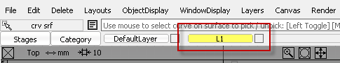
- Double-click the name of the layer in the Layer Bar to edit it. Change the name to imageref for easy identification.
No objects are in this layer, since the image reference canvases were created on the DefaultLayer. It is a good idea to create new layers before creating the geometry or objects to go on them to avoid objects being left on the DefaultLayer. The Default Layer allows instant organization from a new scene, but it cannot be hidden or made into a reference layer.
- Choose the PickPick Object
 tool (hold + + to show the Pick marking menu, then drag down to Object).
 - Click and drag a selection box around all three canvases in the scene. They are highlighted in white to indicate they are selected.
- -click on the imageref layer in the Layer Bar to show its controls.
- Choose Assign from the menu of controls.
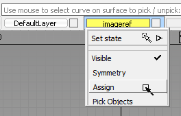
The prompt line indicates that the canvases have been assigned to that layer.
- -click again on the imageref layer and choose the submenu item Set stateReference.
The layer appears brown in the Layer Bar, and the reference image canvases are unpicked. They can no longer be picked interactively like other objects in the scene.
To dim the images in the scene, reduce the opacity of the canvases.
- Press + + to show the View marking menu.
- Drag down to Plane Editor to open the Construction Plane Editor window.
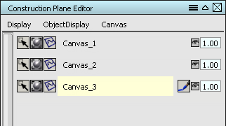
The three canvas planes are shown as layers with control options.
- Double-click in the numeric entry box on the right side of each canvas layer and enter 0.25 to set the Opacity to 25%.
Each canvas dims in all views to the value entered.
- Close the Construction Plane Editor window when all canvases are dim, but still visible.
- Finally, to be sure that the image references and the grids remain in line with each other, verify that the menu item WindowDisplayWindow Sync
 is checked. If not, select the menu item to toggle it.
Save your file
With these preferences and reference images in the scene, it is a good time to save the file for the later work.
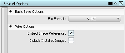
- Choose FileSave As
 to open the Save All Options window.
 - Check the option to Embed Image References to keep the reference images in the file.
- Click Save. The Save Wire file browser opens.
- At the top of the dialog, use the Go menu to switch to the Current Project (typically called demo or new_project).
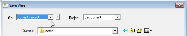
These project folders for various elements have been automatically created in your User Documents folder.
- Use the Project menu at the top of the dialog to Set Current, which changes the file save location to the wire folder for this type of file.
Each time after this that you use Save or Save As, the file goes into this folder.
- Enter vacuum_start as the name of your file, and click Save.
Now that the scene is set up, proceed to the next lesson (Getting Started) to create and modify geometry.