|
In this lesson you define and enclose the vacuum shapes with advanced surfaces and trims, and modify the shape of those volumes.
Objectives
- Simplify surfaces while maintaining continuity
- Define volumes for later modification
- Create and modify transition surfaces
- Align to curves and the symmetry plane
Prerequisites
- You have completed the Create and evaluate surfaces lesson.
 Watch video
Create the side of the handle
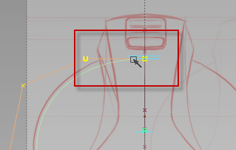
First create the side surface for the handle from the existing surfaces and a new curve.
- Create a New Layer, and rename it handlecurves.
- Choose Curves
 New CurvesNew Edit Point Curve
 .
.  +
+ +
+ and drag to curve snap the first edit point to the bottom trim edge of the back surface.
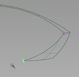
- Curve snap the second edit point to the trim edge of the front surface.
- Pick Nothing.
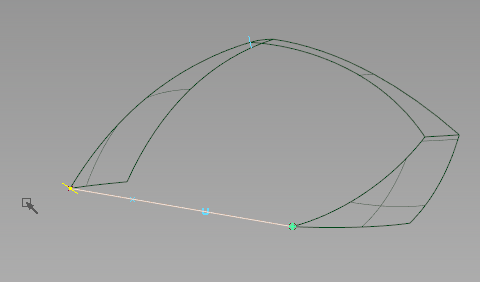
- Choose PickPoint Types CV
 , and drag-select the interior CVs of the new curve.
 - Choose TransformMove
 , and
, and  -drag the CVs along the Y axis, toward the centerline.
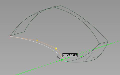
You can create the side surface for the vacuum from the region that these three surfaces and the curve define.
- Create a New Layer, and rename it handlesurfaces.
- Choose SurfacesBoundary SurfacesSquare
 , and open the options box.
 - Click the Continuity button and set all boundaries to Free.
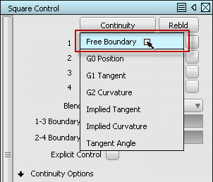
- Pick the surface edges as boundaries, and then the curve. A four sided surface is created.
- Pick Nothing.
- Toggle Shade (Fast)
 to examine all of the surfaces.
Evaluate and simplify the surface with History
- Pick the square surface.
- Check the number of spans in the Control Panel.

The number of surface spans is excessive, and can cause problems in later modeling operations.
- Choose Object EditQuery Edit
 .
. - on the square surface. The options for the tool that created the surface are opened, and you can modify the surface parameters interactively.
- In the Square Surface options box, under Control Options, check Continuity Check.
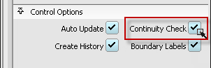
Locators are created where the surface touches another surface.
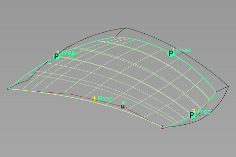
A green "P" indicates the surfaces touch each other along that edge within the set tolerances.
- Check the Rebld option for each input boundary.
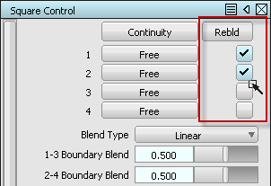
The number of spans are reduced as each boundary is rebuilt, and continuity is maintained.
Note: The Alias Surface and Automotive products include an advanced option for tools like the Square Surface, called Explicit Control. This allows the definition of exact numbers of spans and their degree, which can further simplify the surface. - Close the Options box and Pick Nothing.
- Choose DeleteLocators
 to remove the continuity display.
 - FileSave As
 the model as vacuum_part4.wire.
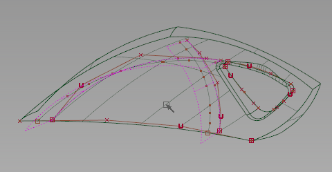
Create the interior of the handle
- Make the imageref layer visible, and make the handlecurves layer active.
- Choose CurvesNew CurvesNew Edit Point Curve.
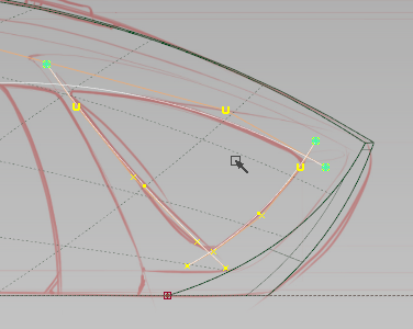
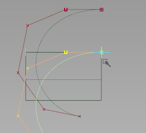
- In the Left view, click-drag to draw the internal arc with three edit points.
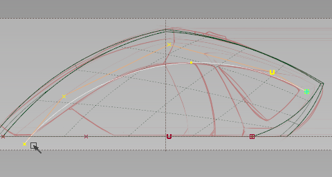
- Pick Nothing, then continue to draw two more intersecting curves to define the interior region of the handle.
- Pick Curves and drag-select these three curves.
- Choose Curve EditCutIntersect Curves and Detach.
- Click Go.
The three curves split where they intersect.
- Pick Curves and drag-select the smaller exterior corner pieces.
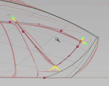
- Choose DeleteDelete Active.
- Choose Curve EditCreateFillet Curves
 .
. - Pick the curves at the back corner to fillet their intersection.
- Type a radius value of 2 and press Return to see the fillet.
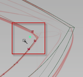
- -click-drag to adjust the radius to match the sketch, or type a precise radius amount.
- Click Accept when the fillet radius is correct. Note: Once you click Accept, the source curves are trimmed without History. You can adjust the fillet radius later with History, but you can make it larger only.
- While the Fillet Curves tool is still active, repeat the process to fillet the other two corners.
- FileSave the model as vacuum_part4.wire.
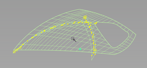
Draft the interior curves
- Hide the imageref layer, and make the handlesurfaces layer active.
- Choose SurfacesMulti-surface Draft
 and open the options box.
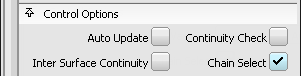
 - In the Pick Mask section, uncheck all options except Curves.

- In the Control Options section, check the Chain Select option.
- Click any section of the interior curves or fillets to select them all.
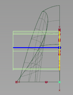
- In the Draft Vector Options section, set the vector to the Y axis.
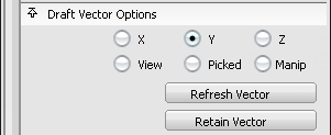
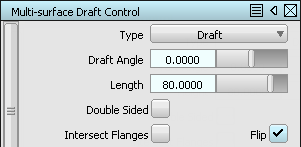
- Set the Length to 80 and check the Flip option if the blue vector line is pointing toward the centerline.
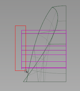
- Click the Build button. A new draft is built that extends beyond the side surface.
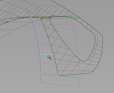
Create transition surfaces for the handle
Create transition surfaces to blend surfaces that flow in different directions, like the side of the vacuum and the interior handle surfaces.
- Choose SurfacesMulti-Surface FilletSurface Fillet
 .
. - In the Left view, drag a pick box around the handle interior Draft surfaces as the first surfaces.
- Click Accept.
- In the Perspective view, pick the square surface as the second surface.
- Click Accept.
Two arrows appear to indicate the normal direction of the Surface Fillet for each set of surfaces.
The directions are outward for the Draft surfaces, and inward to the centerline for the Square.
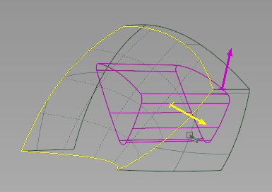
- Click Build.
The Fillet surfaces are built around the edge of the intersection, but you can adjust the radius.
- Type 5 to set the radius to a smaller value.
- Click Update to rebuild the fillet.
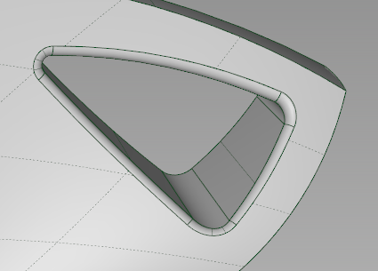
- Pick Nothing, then toggle Shade (Fast) to examine the transition surfaces.
Modify the handle fillets
Construction History allows for complex surfaces to be updated, even long after they have been built.
- Choose Object EditQuery Edit.
- -click any of the Surface Fillet surfaces.
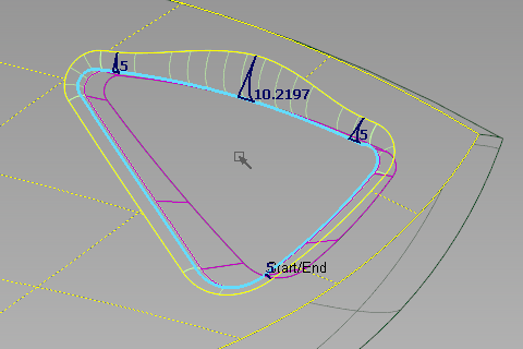
- Check the Variable Fillets option.
A blue radius edge appears along the fillet.
- -click-drag near the center of the top edge to create a radius with a value near 10.
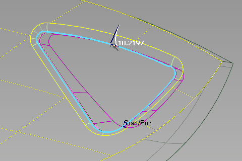
- Click Update.
A new fillet is created with a variable radius, however this radius is not easily controlled.
- Click either end of the top edge to create new radii with default values of 5.
- Click Update.
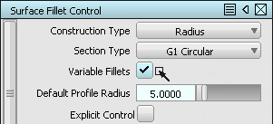
- In the options for the active Surface Fillet, change Section Type to G2 Curvature.
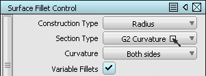
- Click Update.
- Pick Nothing, then choose Diagnostic ShadingUser Defined Texture and tumble the view to examine the reflections along the transition.
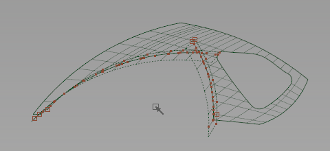
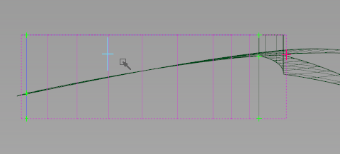
Draft the front boundaries
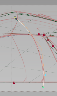
- Switch to the Left view.
- Make the layers imageref layer visible, and make the handlecurves layer active.
- Choose CurvesNew CurvesNew Edit Point Curve.
- Click-drag three edit points along the interior curve shown in the following image.
- Hide the layer imageref, and create a layer named frontsurfaces.
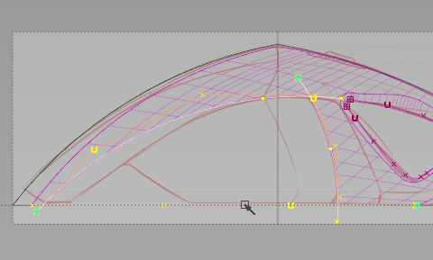
- Choose SurfacesMulti-surface Draft and open the options.
- In the Pick Mask section, uncheck all options except Curve.
- Pick the two profile curves for the front section as shown in the following image.
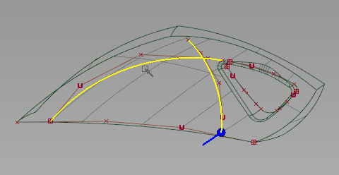
- In the Draft Vector Options section, set the vector to the Y axis.
- Set the Length to 80 and check the Flip option if the blue vector line is pointing toward the centerline.
- Click the Build button to build the Draft.
- While the draft surfaces are still selected, choose Surface EditCreate CurvesOnSurfaceIntersect
 .
. - Pick the Square surface to intersect with.
- Make the imageref layer visible, and set its state to Pickable.
- Pick Canvas_1 (the Top view image) to intersect with.
Curves-on-surface are created only on the draft surfaces where the canvas plane intersects them.
- Set the state of the imageref layer back to Reference.
Trim the front regions
- Pick Object and click the draft surfaces and the square surface to pick them.
- Choose ObjectDisplayHide Unselected to isolate these items in our workspace.
- Pick Nothing.
- Choose Surface EditTrimTrim Surface
 and pick the Square surface as input.
 - Click to define the front bottom region, and click the Discard button.
- Pick Surface and click the back draft surface.
 Note: Pick Object selects both draft surfaces as a single object, and Pick Surface only selects one component surface at a time.
 - Choose Surface EditCreate CurvesOnSurfaceIntersect and pick the front draft surface to intersect with.
- Choose Surface EditTrimTrim Surface and pick the back draft surface as input.
- Click to define the interior region (closest to the centerline).
- Click the Keep button.
- While the Trim tool is still active, switch to the Top view and pick the front draft surface as input.
- Click to define the interior region of this surface.
- Click the Keep button.
- Examine the finished surfaces, and choose ObjectDisplayVisible
 to display the other objects in the scene.
 - FileSave the model as vacuum_part4.wire.
Draw the final motor box profiles
Our initial motor box and waste bin helped us to judge the volume, but now we will follow the sketch for profiles.
- Create a layer, and rename it to frontcurves.
If the layers in the Layer Bar are disappearing on the left side, click and drag on the Layer Bar scroll icon to make them visible again, or choose Windows
Object Lister and then choose LayersToggle Layer Bar to hide the Layer Bar.
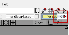
- Use Pick Curve to pick the three source curves for the front square and draft surfaces.
- Assign these curves to the frontcurves layer and make it the active layer.
- Hide the handlecurves layer and the frontsurfaces layers to minimize what is shown.
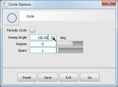
- Choose CurvesPrimitivesCircle
 and open the option box for the tool.
 - Uncheck the Periodic Circle option, and set the Sweep Angle to 180 degrees.
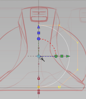
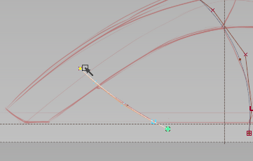
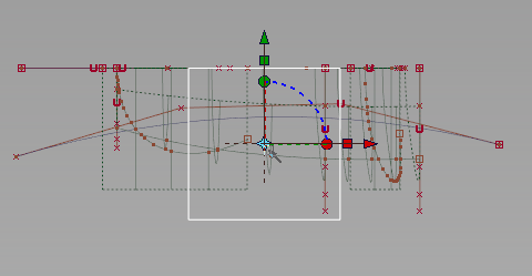
- In the Front view, use grid snap and click-drag the semicircle along the centerline until it is close to the center of the motorbox volume.
- Click the rotation disc on the manipulator.
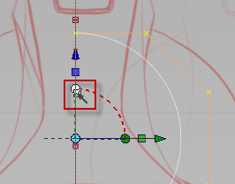
- Type 180 and press Enter to flip the semicircle to the working side of the symmetric workspace.
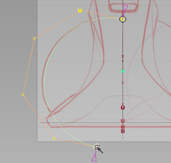
- Choose Curve EditModifyTransform Curve
 .
. - Click the button for Rotate and Scale.
- Drag the bottom handle until the semicircle matches the sketch.
- Choose Object EditAlignSymmetry Plane Align
 .
. - Click the top edge of the circle, near the centerline.
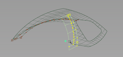
Position the profiles
- Choose CurvesNew CurvesNew Edit Point Curve.
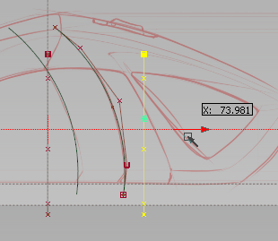
- In the Front view, click-drag three edit points along the front motorbox edge as shown in the following image.
- Choose SurfacesMulti-surface Draft.
- In the Left view, pick the front and back profiles of the motorbox.
- In the Multi-surface Draft options box, set the Angle to 0, the Length to 80, and the Vector to Y. If the surface builds on the symmetric half, check the Flip option.
- Click Update to begin the Draft.
- Pick Nothing, then Pick Object the new Draft surface and the Circle.
- Choose ObjectDisplayHide Unselected
 .
. 
- In the Left view, Pick Nothing, then Pick Object the Circle.
- Choose TransformLocalSet Pivot
 and magnet snap the pivot to the top CV of the circle.
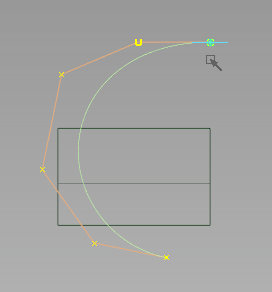
- EditCopy
 the circle, and EditPaste
 a copy into the scene.
 The copy is placed exactly over the original, so only Paste once.
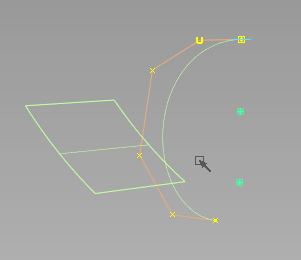
- Choose TransformMove (+ M) and curve snap the copy to the top corner of the draft surface.
- Choose TransformScale
 and scale the curve to about 55% of its original size.
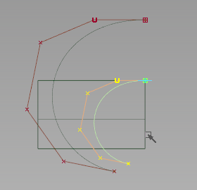
- EditPaste a second copy of the larger circle into the scene.
- Choose ObjectDisplayVisible to bring back the contents of the visible layers.
- In the Left view, Move the copy with the until it is near the handle region.
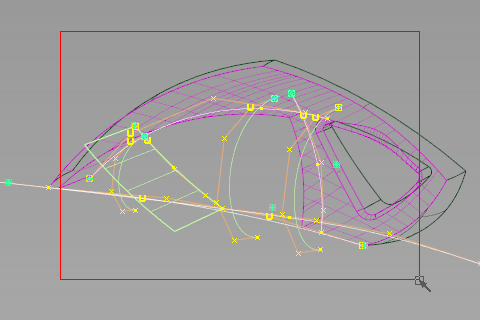
Skin the new motorbox volume
The skin tool can create a controlled surface from a few carefully positioned curves.
- Pick Nothing, then Pick Object and pick the front draft surface.
- Make the frontsurfaces layer visible and active.
- Assign the picked surface to the frontsurfaces layer.
- Pick Curves and drag a pick box around all of the visible profile curves.
- Choose ObjectDisplayHide Unselected.
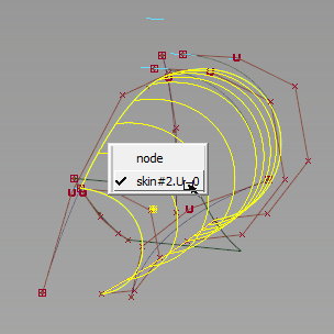
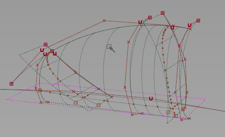
- Choose SurfaceSkin
 and Shift-pick each circle from back to front.
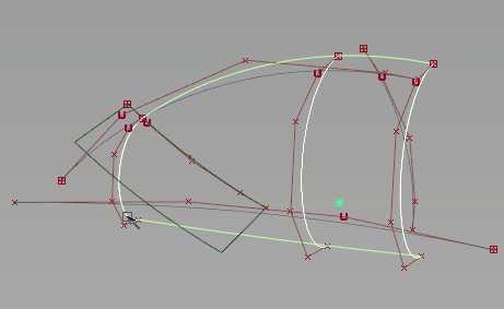
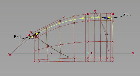
- Choose Object EditAlignAlign
 , and pick the top edge of the skin surface.
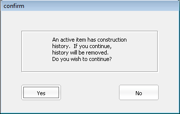
This Align tool removes the history from the Skin.
- Click Yes to continue. The top edge is highlighted for alignment.
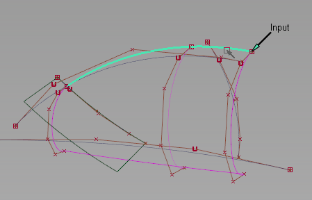
- Pick the upper profile curve which is close to the edge to be aligned.
The entire top edge of the skin is aligned with the curve.
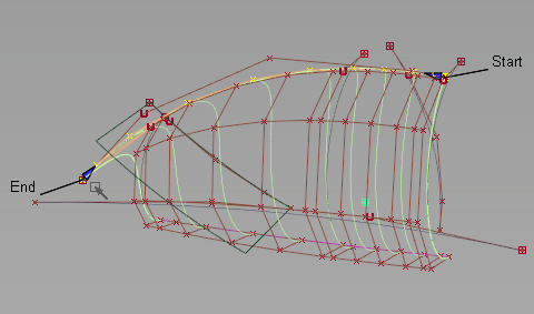
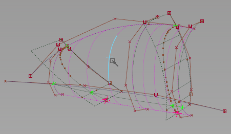
- In the Left view, click-drag on the End handle until it snaps to the intersection of the front profile.
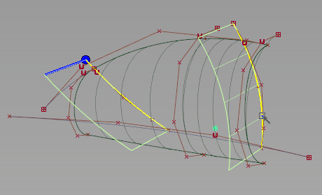
- Choose Object EditAlignSymmetry Plane Align and pick the same top edge of the skin surface from the pick chooser.
- Again, click Yes when warned about the removal of construction history.
The surface is once again aligned for symmetry.
- FileSave the model as vacuum_part4.wire.
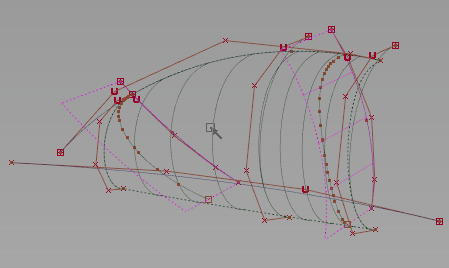
Intersect and trim the surfaces
- Choose Object EditQuery Edit and pick the small draft surface.
- With the Multi-surface Draft option box open, click the back profile curve, and click Update.
The second profile is added to the draft, and a second surface is created.
- Choose Surface EditCreate CurvesOnSurfaceIntersect.
- Pick the Skin surface to intersect with the draft surfaces.
- Choose SurfacesPrimitivesPlane
 .
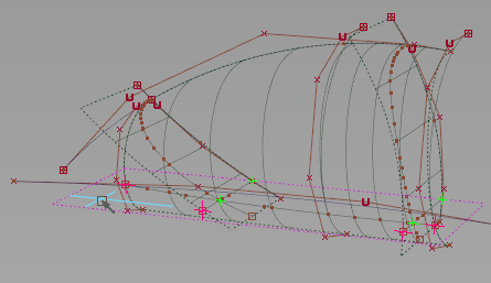
. - In the Top view, use grid snap to position the plane in the middle of the new motorbox surfaces.
- Click the red square scale manipulator and drag to scale the plan to fit the other surfaces.
- Choose Surface EditCreate CurvesOnSurfaceIntersect and click the skin and draft surfaces to intersect with the plane.
- PickObject and pick the modified skin and the draft surfaces.
- Choose Surface EditTrimTrim Surface and pick the plane.
- Click in the exterior edge of the plane, and click the Discard button.
- While the Trim tool is still active, click in the interior region of the skin, and click the Keep button.
- Pick the draft surfaces to trim next, and click in the interior regions.
Click the Keep button.
- Create a layer and name it motorsurfaces.
- Assign the trimmed skin, plane, and draft surfaces to the new layer.
- Choose Object DisplayVisible to return the hidden objects to view.
- FileSave the model as vacuum_part4.wire.