You should see JT in the File Formats pull down menu for File > Export > Active As and File > Save As.
AlToJt is a command-line utility which you can use to translate a wire file to JT format from the Command Prompt window, without running Alias. Type AlToJt -h to see a list of all available options and their definitions.
Below is a description of all the options in the option window, as well as their command-line equivalent.
- Organize Data First By
-
This option allows you to organize your data by GEOMETRY, SHADER, LAYER or SBD structure type.
GEOMETRY – One DirectModel node object (.jt file) is generated for each geometry object. There is a one to one correspondence between a geometry object and its DirectModel part.
Command-line equivalent: -e1g
SHADER – One DirectModel node object (.jt file) is generated for each Alias shader.
Command-line equivalent: -e1s
LAYER – One DirectModel node object (.jt file) is generated for each Alias layer.
Command-line equivalent: -e1l
SBD Structure – The SBD structure in Alias is first translated to an assembly structure in DirectModel, then one DirectModel node object (.jt file) is generated for each geometry object.
Command-line equivalent: -e1b
- Organize Data Second By
-
This option allows you to organize your data in a multi-level hierarchy structure. Organize Data First By creates the first hierarchy level, and Organize Data Second By lets you control how the second level of the hierarchy is constructed. This option is only available when Organize Data First By is set to SBD Structure, SHADER or LAYER. The following table shows the possible combinations:
Organize Data First By Organize Data Second By Geometry None Shader Layer / None Layer Shader / None SBD Structure Layer / Shader/ None Command-line equivalent: -e2b for SHADER and -e2l for LAYER.
- Sort by Name
-
This option allows you to organize your geometry data (bottom level of the hierarchy) alphabetically by name.
It is only available when Organize Data First By is set to SHADER, or when it is set to SBD Structure and Organize Data Second By is SHADER or LAYER.
- Create a Single File
-
This is turned on by default, so that wire files are converted into an assembly file and a folder containing a single file per part.
Command-line equivalent: -g to turn the option on.
- Export Curves
-
This option is turned off by default so that 3D curves and curves on surface are not exported.
Command-line equivalent: -wc
- Export Invisible data
-
This option is turned off by default so that invisible geometry is not exported.
Command-line equivalent: -wi
- Export Templated data
-
This option is turned off by default so that templated geometry is not exported.
Command-line equivalent: -wt
- Export Lights
-
This option is turned on by default so that all light information is exported. This forces the translator to process Alias lights.
If a light is assigned a name in Alias, the name will be exported as well.
Command-line equivalent: -xl
- Export Shaders
-
This option is turned on by default so that all shader information is exported. When turned off, the translator ignores shader information.
If a shader is assigned a name in Alias, the name will be exported as well.
Command-line equivalent: -xs
- Export Textures
-
This option is turned on by default so that all the texture information is exported. When turned off, the translator ignores texture information.
If a texture is assigned a name in Alias, the name will be exported as well.
Command-line equivalent: -xt
- Export Symmetry
-
This option applies to layers that have mirror symmetry turned on in Alias.
Off: The instanced geometry is not exported. This is the default.
Merged: The instanced geometry is duplicated as additional geometry through the JT translator (AlToJt). Each instance is merged into the same node as its original geometry in the JT viewer program.
Command-line equivalent: -ws
Unmerged: The instanced geometry is duplicated as additional geometry through the JT translator (AlToJt), but the original and instanced geometry are located in separate nodes in the JT viewer program.
Command-line equivalent: -wsu
The Unmerged setting can be over-ridden on a per layer basis based on the layer name. If the layer name ends with -jtmrg, and symmetry is on for that layer, then geometry in that layer will be exported as if Export Symmetry was set to Merged.
- Create Logfile
-
This option is turned on by default so that a log file is generated. The log file contains the time of the conversion, and the names and types of converted objects.
Command-line equivalent: -l
- Stitch Surfaces
-
This option is turned off by default. When turned on, the B-Rep faces are sewn together along shared edges within a single part. This eliminates some problems with gaps between surfaces. However, this does not sew edges between two adjacent parts, but only between surfaces within a single part.
Command-line equivalent: -q to turn the option on.
- Scale Factor
-
The default value is 1.0. 0.5 reduces the size by half; 2.0 makes it twice as large. This allows you to manipulate the scale on export.
Command-line equivalent: -s
- Texture Image Resolution
-
The default is 128. This specifies texture file image resolution and is used during 3D (Solid or Environment) texture conversions. Valid resolutions are 8 to 8192.
Command-line equivalent: -u
- Geometry Type
- Choose Polygon to export only the polygons or Polygon + Brep to export the Brep representation as well.
- Brep Type
-
This option only appears if Geometry Type is set to Polygon + Brep.
Choose XT Brep to create parasolid Brep data. You can also select JT Brep.
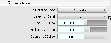
Tessellation Options
- Tessellation Type
-
You can choose between three different tessellators:
Fast – uses the same tessellator as Hardware Shade with the Fast option selected. This is the default. Command-line equivalent: -to.
Accurate – uses the same tessellator as Hardware Shade with the Accurate option selected. Command-line equivalent: -ta. (This replaces the old AG tessellator.)
Current – this should give you the same tessellation as in Hardware Shade when Show Triangles is on (this option appears when Quality is set to User defined). Command-line equivalent: -td.
- Tessellation Tolerance
-
This option applies to Fast and Accurate tessellation modes only. Command-line equivalent: -t <tol> (where tol value is expressed in centimeters).
Note: Current surface tessellation uses the Tolerance value from the Hardware Shade option window (this option appears when Quality is set to User defined). - Levels of Detail
-
This option applies to Fast and Accurate tessellation modes only. It indicates the number of tessellations that will be saved in the JT file (1, 2, or 3). The default is 1.
- LOD 0 tol
- Use this slider to set the tessellation tolerance for the first tessellation. The default is 1.0
- LOD 1 tol
- This slider only appears if Levels of Detail is set to 2 or 3. Use it to set the tessellation tolerance for the second tessellation. The default is 2.5.
- LOD 2 tol
- This slider only appears if Levels of Detail is set to 3. Use it to set the tessellation tolerance for the third tessellation. The default is 10.0.
LOD labels
Labels can be assigned to the different LODs (tessellations) and appear in the option window next to the sliders.
Only the first 15 characters of the label names appear in the option window, although all are saved in the JT file. Allowed characters are letters (upper and lower case), numbers, underscore ("_") and white spaces.
Use one of the following methods to set labels:
- Set these environment variables to the required names:
- ALIAS_JT_LOD0_LABEL (first LOD)
- ALIAS_JT_LOD1_LABEL (second LOD)
- ALIAS_JT_LOD2_LABEL (third LOD)
For example: ALIAS_JT_LOD0_LABEL=Fine
- Un-comment and set the following name-value pairs in the dt_jt.v.scm file (if you have administrator privileges):
(ui-symbol "mo_eai_tess_lod0_label" "Fine")
(ui-symbol "mo_eai_tess_lod1_label" "Medium")
(ui-symbol "mo_eai_tess_lod2_label" "Coarse")
This file is found under the Alias installation in ALIAS_LOCATION\Scheme\Modeling where ALIAS_LOCATION is typically Program Files\Autodesk\Alias2014.
Note: Labels specified through the scheme file override the environment variables.