CAD – it is usually recommended to stitch data before exporting it to CAD (this may vary, depending on the target CAD application or the file format chosen).
In this process, stitch the data to generate a shell. Then with only the shells selected, choose File ExportActive As. The option dialog enables you to select different file formats and appropriate option settings that are based on the selected format.

|
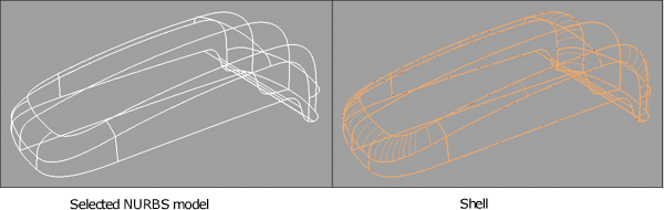
Surface Edit Creates a special object called a shell from a group of surfaces, in preparation for export to a CAD package or STL. Gaps in a shell are highlighted in yellow (or in pink when the shell is not selected). These gaps are usually the result of gaps in the original NURBS model. A user-defined stitching tolerance can be set by unchecking Use Construction Options in the Stitch tool, to try coping with these gaps. Sometimes the NURBS geometry itself will need to be fixed. |

|
Evaluate
Checks all, visible, or picked objects for common problems that may prevent data transfer. It is useful to check the data with Check Model before shelling or exporting. The tool can identify short edges, multiple knots, internal tangent discontinuities, and so on. It includes check boxes for G0, G1 and G2 continuity. |

|
To export data to STL, select the surface, shell, mesh, or any combination of these and select File Data needs to be stitched before it can be exported to STL. The STL can be refined as required by using the tolerance option exporting data to either STL ASCII or Binary formats. STL files can be read back into Alias for evaluation since Alias reads in STL ASCII and Binary files. |