Legacy tutorial posted on the old Alias Design Community site on December 2, 2005.
Step 1
With surface modeling, often there is a need for curvature continuous modeling. This is true especially when it comes to the automotive industry's special needs like "G2" and "G3" flying around. There is a lot of confusion surrounding this area when these levels of quality are needed; if they have been already achieved and how they are evaluated in the major CAD packages.
To shed some light on the aforementioned, this tutorial will investigate the background of curvature calculation and evaluation in StudioTools v.12. In addition, the information covered here will help the user understand tolerance settings for curvature and how to apply them in their daily surface creation work. Lastly, this tutorial will demystify the discussion about achieving G2 or G3 continuity within StudioTools, as well as possibly help users to better defend their surface models when presenting to their superiors.
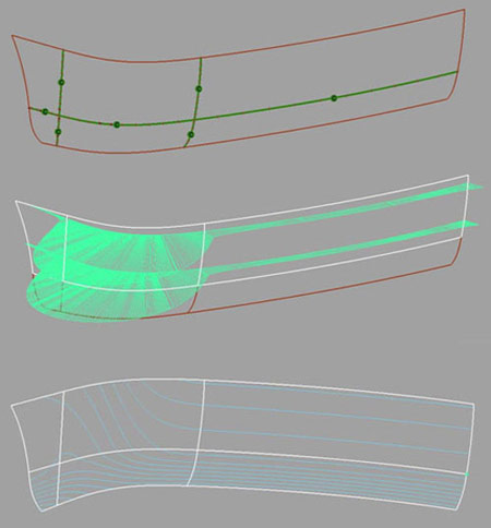
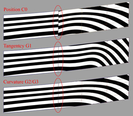
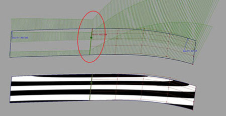
The picture below shows the various ways to evaluate curvature continuity on the same model. Each way has its need, but they all say completely different things about the surface continuity of this model.
In surface modeling, there are three basic continuity conditions between curves and surfaces.
The lowest continuity level is Position, C0.
This continuity is absolute. It measures the gap between two surfaces. It's just a direct measurable value of a distance. A direct measurable tolerance is given to that.
The next continuity level is Tangent, G1.
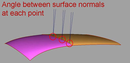
This continuity is absolute as well. It's been measured by the angle of the surface normal of both surfaces at the measuring point.
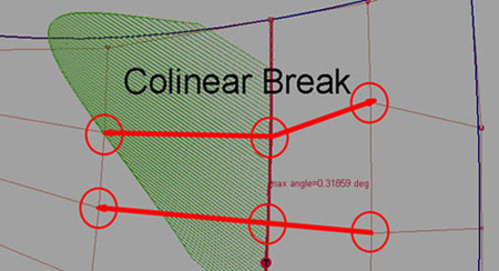
There is another aspect of tangency. It's about the skewing of the tangent hulls.
This is a measurement about the co-linearity of the tangent CV's which plays a role in Class-A level advanced surfacing.
Tangent continuity between surfaces describe a basic quality of the appearance of a highlight across the surface boundary.
The minimal quality that can be achieved with tangent continuity is a highlight that matches on both sides of the surface boundary. But there is no guarantee that the highlight flows without a peak.
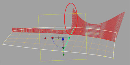
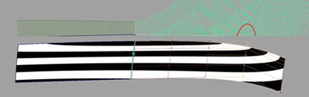
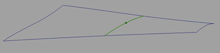
The picture above shows a curvature comb measurement using the Dynamic Section Tool. Because between the two surfaces there is only tangency achieved, the curvature comb between both surfaces will have a step.
When milling this surface, once it is set out in clay, the highlight peak will be visible. Other than this, people can feel the curvature comb step across the two surfaces when they stroke this area with their hands. For many designs, this quality is not enough.
That's why tangency is not enough for defining highlights across surface boundaries. To model highlight continuity, we need to talk about curvature continuity
So now it comes into the curvature discussion - the topic of this tutorial.
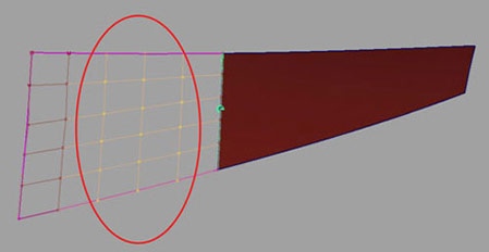
The basic curvature level, the common level is called G2. This level affects the third row of CVs on the surface at the edge where continuity was measured.
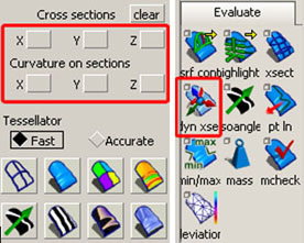
That's why we are going to use the curvature comb as the final evaluation tool.
For both curvature continuity levels (G2 and G3), it is necessary that there is no step in the curvature comb. For that, the cross sections from the Control Panel or the Dynamic Section Tool from the Palette can be used.
Analyzing the G2 result the curvature comb doesn't necessary have to be smooth, means without a peak.
It is important to note that this defect is not detectable when checking the surfaces with the diagnostic shader.
All the curvature continuity methods are only giving information about the continuity between surfaces. This information is not enough to judge the surface quality of the entire surface model. It doesn't matter if the user checks for G2 or G3 continuity.
The smoothness of the surface inside and the balance of each surface to each other have the same importance as the continuity at the boundaries. The problem is that final checking tools in StudioTools (like the mcheck Tool) cannot evaluate this second part. The user has to verify this using another functionality.
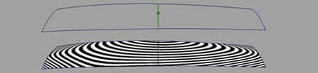
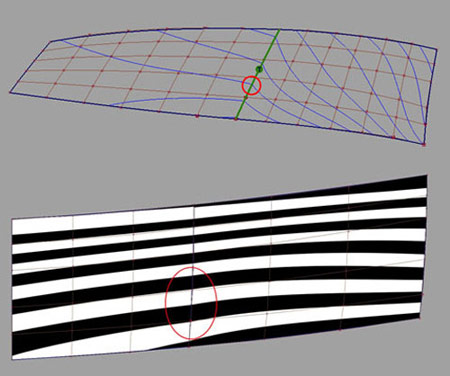
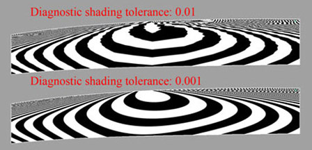
The picture above shows a surface set that was measured curvature continuous to each other. Even the diagnostic shader shows a quite good highlight.
But as you can see in the next picture, the curvature plot shows the bad quality of both surfaces together. The curvature comes to a peak at the patch boundaries and the acceleration of the curvature within both surfaces is not homogenous at all.
This cannot be evaluated just by trusting the curvature continuous locator or the diagnostic shader. For further surface quality, you need to investigate a bit deeper.
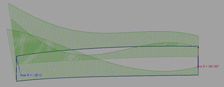
Asides from the curvature comb quality, there is another problem. The green locator shows a measurement within a certain tolerance. The next chapter of this tutorial will show why it is not guaranteed that this positive curvature measurement will be accepted by the tolerance of other CAD packages.
Step 2: Curvature Evaluations in Studio v12
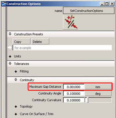
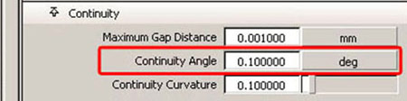
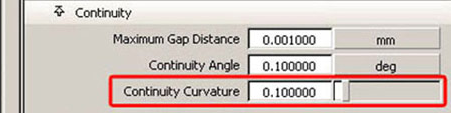
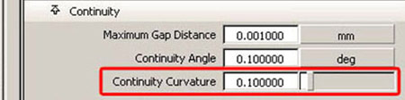
In Studio v.12, the curvature continuity has a tolerance (default 0.1) that decides the curvature measuring result into achieved or not achieved. It's a digital decision but in reality, the curvature evaluation is much more relative and special for each case. In reality it's analog.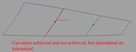
In reality, the user can accept curvature continuity even with little breaks because the highlight picture might still look good or acceptable. Insisting on the same curvature value on both sides of the surface boundary would probably cost too much mathematical effort to build both surfaces. That's why the user decides not to go for 100% curvature. This approach cannot be achieved with the tolerance that was given for the curvature evaluation.
Unfortunately, StudioTools offers this digital approach in curvature evaluation and the majority of users need that for their comfort. That's why this tutorial tries to explain the mathematical background of curvature evaluation in StudioTools v.12, to make the user at least aware about the digital information a curvature continuous locator gives.
Let's say a surface set has been measured curvature continuous within tolerance.
This looks good to an average user; because the green color of the curvature locator indicates that everything is all right. The truth is, that the user can be sure about curvature within TOLERANCE. But that doesn't necessarily mean that the highlights are good or that other CAD systems will accept this measurement as good either. The tolerance in StudioTools v.12 is absolute. Using bigger radii, the absolute curvature break becomes really small and falls below the tolerance. That's why we will have a deeper look into the mathematical calculation of the curvature in Studio v12.
CURVATURE (in Stduiov12) = ABSOLUTE 1/Radius1 - 1/Radius2
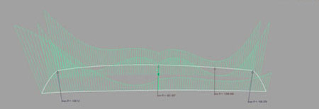
The curvature of both surfaces will be calculated at certain points along the surface boundary that has to be measured. The picture below illustrates one of these points.
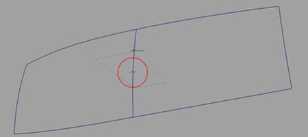
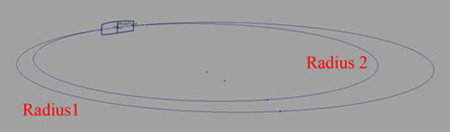
The two surfaces would be 100% curvature continuous if the two circles would have the same radius. In the picture they differ, and that means that that difference specifies a curvature break.
For example some common radii in automotive surfacing could be like this:
Radius1 = 5000 mm
Radius2 =2000 mm
The CURVATURE VALUE ( 1/Radius) would be 0.002
This value seems small. But the real difference of the radii of both circles is 3000 mm, which is huge.
But the tolerance setting in StudioTools v12 is by default 0.1. In this case the 3000 mm difference of the radii would result in a curvature break of 0.002 and this would be WITHIN the tolerance and the user would see a GREEN locator.
This is not good! Such a curvature break should be detected as a break, but with the default tolerances it won't.
I would like to call this system kind of "curvature forgiving".
Here is an interesting experiment to underline this effect:
Using two relative flat surfaces that are curvature continuous aligned (default), one of the third "curvature CV's" will be moved in normal direction.
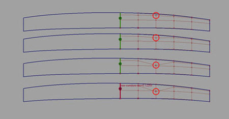
The CV can be moved a long way until the curvature locator shows a break. This is unusual for the majority of CAD packages and shows that the default tolerance is way too high.
Anyhow, the curvature has been calculated precisely, but the interpretation of this result has been done by the software and the tolerance setting of 0.1. The curvature error is quite big, although the software says its curvature is continuous within tolerance.
It becomes obvious that the user has to develop skills to judge the curvature evaluation result by themselves.
There are two good and sophisticated ways to evaluate the smoothness of the highlight flow across surface boundaries:
Highlight shaders
This is quite a relative and analog method. The appearance of the highlight depends on the quality of the tessellation, and on the quality of the display.
Curvature combs
This is a precise, digital evaluation method. The curvature combs are matching or not. There is no other interpretation.


Conclusion
The curvature continuity evaluation in StudioTools is digital, based on a tolerance. Other then Position and Tangent continuity, Curvature continuity is relative and should be modeled and judged by the specific need of each surfacing situation. The red and green curvature locator doesn't always give a useful measurement result, because the measurement method is not the right one, or the tolerance is not appropriate.