The following workflows describe how to use the Align tool that we introduced in AliasStudio 2009. To use the previous version of the tool (renamed Align 2008), see Workflows for Align 2008.
Like its predecessor, the Align tool moves or reshapes a curve or surface to achieve positional, tangent, or G2 curvature continuity with another curve or surface. Additionally it offers G3 curvature continuity. It also provides a simplified interface, direct interaction through the use of manipulators, and superior output.
If you have turned on Face selection in Preferences > Selection Options, the Align tool lets you select surfaces by clicking inside the wireframe. If a surface edge is expected, the tool automatically determines the closest edge to the mouse position.
Align surface edges
- Choose Object Edit > Align > Align

 .
. Edge is the default Alignment Type.
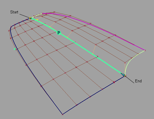
- Click the edge of the surface you want to align (the Input).
- Click the edge of the surface you want to align to (the Master). This can also be an isoparm, curve-on-surface, or trimmed edge.
- Align the edge with the Position Influence slider to help achieve positional continuity if needed.
When the value of the slider is 0.0, the surface being aligned keeps its parameterization intact. As the slider is moved to 1.0, it attempts to match the parameterization of the Master surface, which results in a better fit.
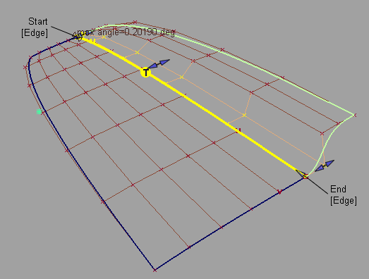
- Set the continuity level to G1 Tangent, G2 Curvature, or G3 Curvature from the Continuity drop down menu in the option window, if desired.
Manipulator arrows allow direct manipulation of the tangent and curvature lengths.
The arrows on the outside of the surface provide independent scaling of the tangent and curvature lengths on each side. The arrow in the middle of the tangent or curvature rows moves all the CVs in that row by the same amount.
If the requested continuity is not achieved, try one or more of the following:
- Adjust the Position Influence slider. It will help line up the CVs along the boundary.
- Turn on Tangent Balance to try and match the hull shape of the Master surface, or adjust the tangent lengths along the edges with the manipulators.
- Turn off Explicit Control. This will automatically set the degree of the Input to that of the Master in the direction of the alignment. You can also manually adjust the degree and number of spans through the option window.
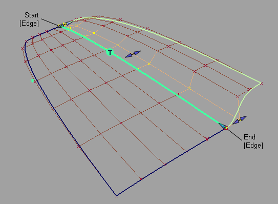
Here Position Influence has been set to 1.0 and Explicit Control turned off to match the degrees. Notice how the CVs now line up perfectly across the boundary.
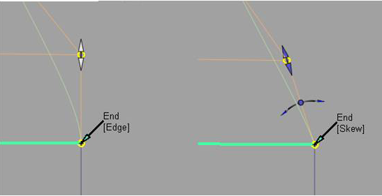
- Change the outside edge alignment by clicking the Edge label to toggle between Skew or Edge Align. Or set Start Align and End Align in the Outer Edge section of the option window.
When Skew is selected, a rotational manipulator becomes visible which allows direct modification of the skew angle. You can also specify a specific Skew Angle value in the option window.
When Edge Align is selected and you are aligning to a natural surface boundary, you can turn on Tangent Balance to adjust the CVs on the tangent row so that the tangent lengths of the Input surface match those of the Master. The same applies to the curvature row CVs if G2 Curvature is on, and to the next row of CVs if G3 Curvature is on.
This aligns one surface to another surface edge, trimmed edge, curve-on-surface, or isoparametric curve.
Undo (![]() + Z (Windows) or
+ Z (Windows) or ![]() + Z (Mac)) can be applied to any manipulator modifications.
+ Z (Mac)) can be applied to any manipulator modifications.
Partially align two surfaces
- Choose Object Edit > Align > Align.
- Click the Partial checkbox in the option window to turn it on.
- Click the edge of the surface you want to align.
- Click the edge of the surface you are aligning to (Master).
The first surface is aligned to the closest points on the second surface.
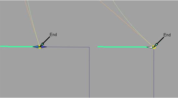
- Modify the location of the endpoints with the Partial manipulators.
The Partial manipulators will change from a double sided arrow to a single arrow when they snap to the end of the Master surface.
You can also use the Start and End sliders in the option window.
Blend an alignment
- After an alignment has been created, click the Blending checkbox in the option window, to turn blending on.
- Select how many Extra CV Rows the blend will apply to.
- Modify the Blend factor to provide more or less influence from the original alignment type.
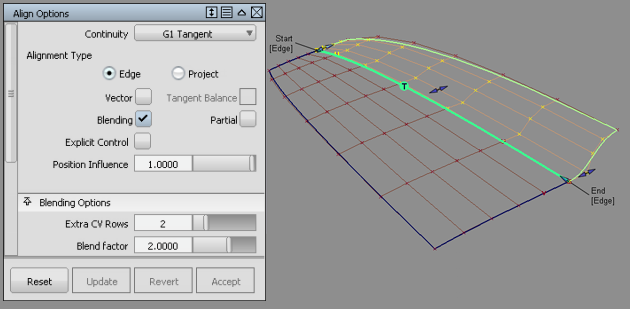
Two rows beyond the tangent row are affected by the Blend factor.
Blending extends the influence of the blend further into the surface or curve.
Blending can be applied to a positional alignment as well to create a smooth distribution of CVs from the alignment edge.
Align using a directional constraint (Vector alignment)
- Establish the edge positional alignment. (See steps 1-4 of Align surface edges).
- If needed, add additional CVs with the Explicit Control sliders.
- Set Continuity to G1 Tangent, G2 Curvature, or G3 Curvature.
- Click on the Vector checkbox to turn the option on.
The Vector Options section appears in the option window.
- Do one of the following:
- Choose X,Y, or Z as the vector direction
- Choose Picked and select an existing vector
- Choose View to use the direction of the current view as the vector direction.
- Choose Normal to use the surface normals as the vector direction. The direction varies according to the position of the CV on the surface.
The tangent and/or curvature CVs are modified along the vector to create the required level of tangency or curvature.
If the alignment cannot be maintained with your choice of directional constraint, the edges of the aligned surface appear as dashed lines.
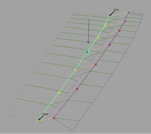
Once a positional alignment has been established, the tangent and curvature rows can be aligned with a vector (directional) constraint.
Sequential alignments can be applied by clicking the Accept button, and removed by clicking the Restore button, at the bottom of the Align option window.
Align by projecting an edge onto a surface (Projection alignment)
- Choose Object Edit > Align > Align.
- Set the Alignment Type to Project in the option window.
- Select the edge to align.
The Vector Options section appears.
- Do one of the following:
- Choose X,Y, or Z as the vector direction
- Choose Picked and select an existing vector
- Choose View to use the direction of the current view as the vector direction
- Choose Normal to use the Master surface's normals as the projection direction, instead of using a single vector.
- Select the surface to align to (Master).
The edge is projected along the defined vector onto the Master surface. A curve-on-surface is created as well, and can be used later for trimming the Master surface.
 Note:
Note:If the edge of the surface being aligned falls outside the boundaries of the Master surface, the alignment cannot be completed successfully.
Note:If the alignment cannot be created using your choice of projection direction, the edges of the aligned surface appear as dashed lines.
Tip:Modification of the projected edge can be made after the alignment by modifying the CVs with Control Panel > Transform CV.
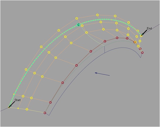
A surface can be aligned to the inside of another surface by projecting the edge along a vector down to the Master surface
Align a surface edge to an entire curve
- Choose Object Edit > Align > Align.
- Click the edge of the surface you want to align.
- Click the curve (Master).
- Click the Partial checkbox in the option window to turn it on. This lets you align to only a portion of the Master curve.
This aligns the length of the surface edge to the length of the curve.
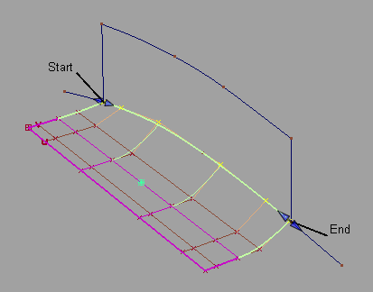
Align a curve end to a surface edge, isoparm, or curve-on-surface
- Choose Object Edit > Align > Align.
- Click the curve close to the end you want to align. Click the surface edge, isoparametric curve, or curve-on-surface at the point you wish to align to.
- Set Continuity to G1 Tangent, G2 Curvature, or G3 Curvature if desired.
The Alignment Type option becomes available. U/V is the default and aligns the free curve to the direction of the surface curve that you selected as the Master.
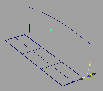
- Set Alignment Type to Vector if you want to align a curve to the interior of a surface, without the need for a curve-on-surface.
The tangent and curvature alignment are then defined by the tangent plane to the surface at the point of contact, and the direction of the vector specified through Vector Options
Alignment Type = Vector: This is equivalent to creating a curve-on-surface on the surface, and aligning the free curve to it.
This aligns the end of the curve to the end of the surface curve.
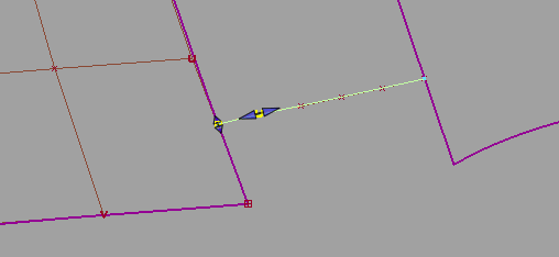
Align two curves
- Choose Object Edit > Align > Align.
- Click the first curve close to the end you want to align.
- Click the second curve close to the end you want to align.
- Set the continuity level by selecting G0 Position, G1 Tangent, G2 Curvature, or G3 Curvature from the Continuity drop down menu in the option window.
Manipulator arrows become available, allowing direct manipulation of the attach point location, as well as tangent and curvature scaling.
- Modify the location of the Attach Point, Tangent Scale, Curvature Scale, or G3 Scale with the manipulators, or control window sliders.
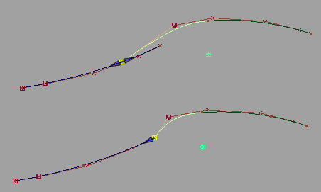
Aligning curves with positional continuity and modifying the Attach Point.
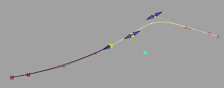
Aligning curves with G2 curvature continuity.
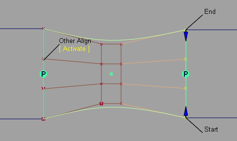
Align both ends of a curve or surface
- Continuity settings at both ends are respected by all options, such as Blending.
- Click the [Activate] label that appears under Other Align on the model, to switch between the two alignment operations.
- Object Edit > Query Edit
 retrieves the construction history for both ends, and you can click the [Activate] label shown above to edit the alignment at both ends. Note:
When a curve or surface is aligned to two masters, it has a single history item as seen with Windows > Information > History View. In this case, clicking the Revert button first reverts the active side (the one you last aligned). The history then applies only to the remaining side. Clicking Revert again deletes the history and returns the input geometry to its original shape.
When aligning both ends of a curve, or opposite edges of a surface: