Legacy tutorial posted on the old Alias Design Community site on February 14, 2008, by Fridolin Beisert. Original Tutorial From "Learning Design with Alias StudioTools".
In this lesson you will learn how to:
- Use rails to create basic surfaces;
- Project physical curves;
- Create a bevel detail;
- Use draft surfaces;
- Use offset surfaces;
- Project tangent;
- Add details.
Body
1 Top Surface
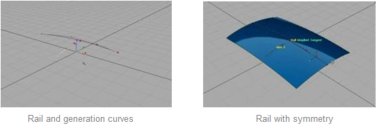
Start by bringing out two curves and create a rail surface.
- Sketch the longer Rail curve in the side view.
- Snap the first CV of the Generation to that curve.
- Continue placing CVs in the back view.
Make sure that the second CV of the generation curve is placed perpendicularly by holding down the MMB.
- Create a rail surface with implied tangency for the centerline.
- Create a new layer for the curves and turn it invisible.
- Assign the rail surface to a new layer and turn on symmetry.
Make sure there are no seams down the center.
Next, turn on the patch precision to better evaluate the geometry. With the surfaces still active, go to:
- Palette > Object Edit > Patch Precision
- Click + Drag anywhere in the window.
The surfaces will get additional patches that do not increase rendering time, but help in evaluating the geometry. You can also enter numbers in the promptline to adjust the amount of patch precision.
2 Bevel
To create a bevel detail, you will sketch out two more curves. These two curves will mark the width of the bevel.
- Sketch out two curves in the top view as shown.
Make sure that each of the first and last two CVs are lined up vertically from the centerline, and that they are within the rail surface.
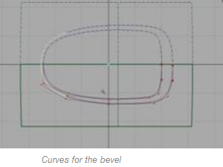
Tip: If you sketch the curves on the layer that has symmetry on, you will get better visual feedback of what the complete outline will look like.
- In the top view, select the surface and project the inner curve onto it.
The curve on surface that is created becomes part of the surface and you will later use this curve to trim the rail surface.
For the second curve, you will change the options when projecting. Make sure you are back in the top view and go to:
- Palette > Surface Edit > Create curves on surface > Project > r
- In the options, select Create Curve and turn off Match Original and Create History. This will allow the newly created curve to have additional CVs so that it will follow the shape of the surface better.
- Click Go.
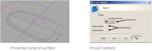
- Click on the second outer curve in the top view.
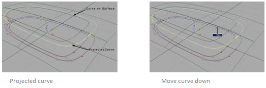
This will create a duplicate that follows the rail, but unlike the curve on surface, it is not attached to the surface, meaning you can move it around.
- Move the projected curve slightly down the Z-axis.
This will create more of an angle between the 2 curves.
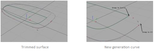
- Trim the rail surface, keeping the inner part.
This will become the face of your product.
- Create a small curve that connects on both the edge of the trimmed surface and the end of the projected curve.
Use the snap-to functions to make sure the CVs touch both curves.
- Repeat the process for the outer side as well so that you will have two generation curves.
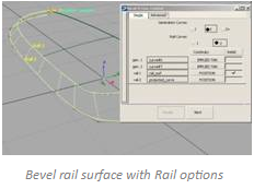
- Go back to the rail Tool options.
Change the number of rail curves and generation curves each to 2, and make sure the continuity for the generation curves is set to implied tangent.
- Click on the small curves first, then the edge of the trimmed surface, and finally the projected curve.
Notice that the rail surface is distorted with many isoparms. This is caused by the trimmed edge.
- In the rail options window, click on the Rebuild for both rail curves.
Notice how the rebuild option optimizes the rail surface and creates cleaner geometry.
3 Draft
Use the Draft Tool to create a surface from the edge of the rail.
- Assign all curves to the curves layer to make them invisible.
- Go to Palette > Surfaces > Draft Surfaces > Draft/Flange >
Leave the option window open.
- Click on the lower edge of the rail and confirm the selection by clicking the Go button.
You will immediately see a draft surface that is pointing upwards.
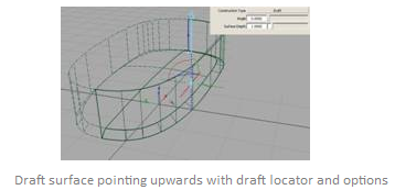
- In the option window, change the Angle to 180º and make sure you have the desired Surface Depth.
The Draft Tool is a quick method for creating accurate linear surfaces.
4 Bottom
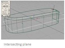
- Create a plane that intersects with the draft surface.
Make sure that the plane fully intersects the draft, but that it only goes to the centerline.
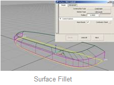
- Use the Surface Fillet tool with a small radius to create the bottom.
- Turn on symmetry on the surface layer to evaluate the finished shape.
5 Bottom
Select only the top surface and create an offset by going to:
- Palette > Object Edit > Offset.
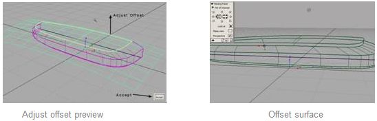
- Use theLMB to adjust the offset distance.
- Click Accept the green preview is slightly above the model.
Alternatively, you can also enter a precise number for the offset in the promptline.
You now have a floating surface as shown. The offset will be used to create an additional raised detail to the design.
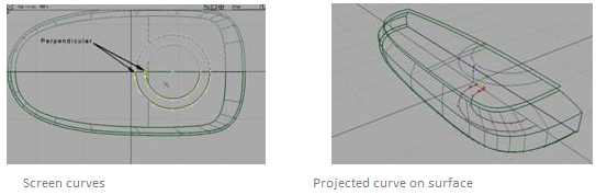
In the top view, create two additional curves for the surface detail. These can be any freeform shape that you like, as long as the second CVs are perpendicular to the X-axis.
- Still in the top view, project the inner curve onto the offset, and the outer one onto the original top surface.
In the project options, remember to switch back to curve on surface.
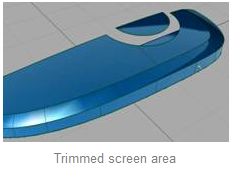
- Trim out both surfaces so that you will get a small floating surface above the cut area beneath it.
- Create two more curves, snapping them to the edges of the trims.
Try to create the new curves with edit points; that way, you only need to snap the first and last CVs onto the trimmed edges
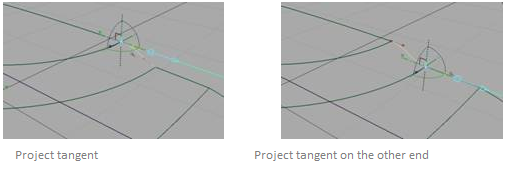
To make the curves tangent to the surface edges, go to:
- Palette > Curve Edit > Project Tangent.
- Click on one end of the curve, then click on the edge of the surface next to it.
The curve will bend to become tangent to the surfaces.
- Repeat the process for the other end of the curve and the other surface edge.
- Repeat the process for the second curve.
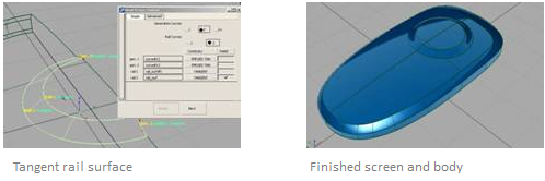
- Use the Rail tool to create the surface.
In the options, choose tangent for the continuity of the rail curves and implied tangent for the centerline. You may also have to use the rebuild option for one of the rails.
- Assign all the curves to the curves layer and turn on symmetry to see the result.
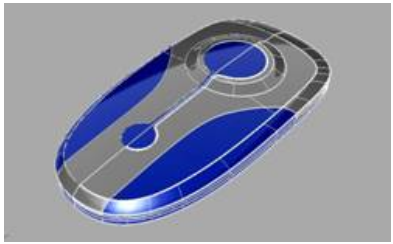
6 Detail
Now that the basic shape is done, try to use the previously covered tools to create some refined details such as partlines, buttons, antenna, camera, etc.
Conclusion
In this lesson, you learned how to apply the tools introduced earlier onto a real project. In addition, you learned how to create draft surfaces and tangent surface details such as the screen area. The last step gave you a preview of the vast options of detailing possibilities.