|
Designs in Alias start from curves and surfaces. This lesson focuses on creating surfaces and understanding the relationship between curves and surfaces, and how Construction History can assist the design process.
In this lesson, you create and evaluate the initial surfaces for the vacuum. This lesson also introduces Construction History and basic organization skills.
Objectives
- Understand relationships between curves and surfaces.
- Use visual symmetry
- Visually evaluate curvature
- Modify surfaces using Construction History
Prerequisites
- You have completed the Get started lesson.
 Watch video
Create the initial surfaces
With the curves placed according to the sketch, you can create surfaces for the top of the vacuum. The curves are linked through Construction History to the surfaces, allowing easy adjustment later on.
- In the Layer Bar,
 -click the motorbox layer and choose the submenu item Set state
 Reference. The initial motor and dustbin shape is only needed for reference as you build further surfaces.
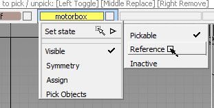
- Press
 +
+ +
+ (Windows), or
  ++ (Mac) to Tumble to a Perspective view of the scene.
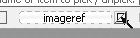
 - In the Layer Bar, click the visibility square to the right of the name of the"mageref layer to hide all of the image reference in the scene.
- Create a New Layer, make it active, and rename it to topsurfaces.
It is a good practice to put curves and surfaces on separate layers.
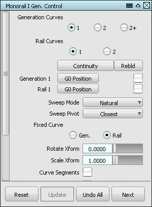
- Choose SurfacesSwept SurfacesRail Surfaces

 .
. - Set Generation Curves to 1, and Rail Curves to 1. This creates a surface by sweeping a single curve profile along a single path curve.
While the Rail Surface options dialog is open, the prompt line says Select generation curve. The tool is active when its options are being edited.
- Pick the central curve as shown.
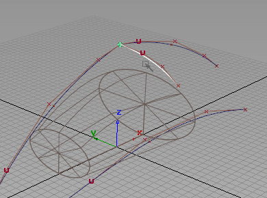
The curve becomes highlighted and the prompt line says Select primary rail curve .
- Pick the front curve that arcs over the motorbox.
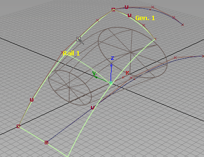
The rail surface is created, and the Rail Surface tool remains active.
- Pick the central curve again for the next generation curve. Note: Due to coincident curves and edges, a pick chooser appears under the cursor when clicked.
From the pick chooser menu, select "curve#4" (the # may be different) to pick and highlight the original curve.
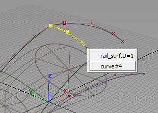
- The prompt line says Select primary rail curve . Pick the back central arc for the rail curve. A second surface is created.
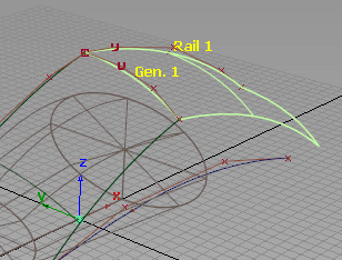
- Pick Nothing, then Pick Object to avoid starting another rail surface.
- Press
 ++ to bring up the display marking menu and drag to the right to select Shade (Fast)
 .
. 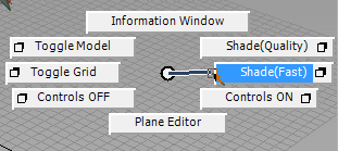
The actual surfaces are easier to see in shaded view.
- FileSave As
 the model as vacuum_part3.wire.
Use display symmetry to show continuity
The goal of modeling only one half of the vacuum is to simplify the process, but take care that the halves line up and appear as a single object when finished. Symmetry and visual analysis tools assist in making adjustments.
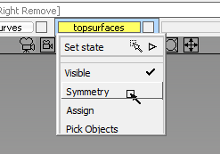
- -click the topsurfaces layer in the Layer Bar, and choose Symmetry from the context menu. This activates visual symmetry for all contents of the layer.
By default, the symmetry display shows symmetric geometry across the X axis. By setting up the sketches and curves so that the center of the vacuum crosses the origin along the X axis, this default symmetry is useful for previewing what the other half of the model would look like.
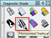
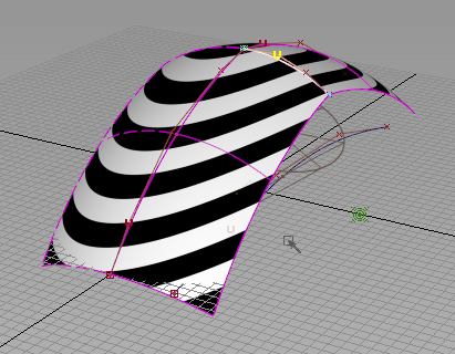
- Choose ObjectDisplay > Diagnostic Shading to open the Diagnostic Shade window, and select the Horizontal/Vertical shading preset to evaluate the continuity of the symmetric surfaces.
The alternating black and white lines (also called "zebra stripes") do not meet as they cross the centerline.
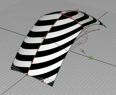
This indicates that the curvature of the surfaces is not continuous. When the halves are later connected, they should form a visually continuous surface.
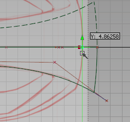
- Switch to the Front view with the ViewCube.
- Choose the Transform CV tool from the bottom of the Control Panel
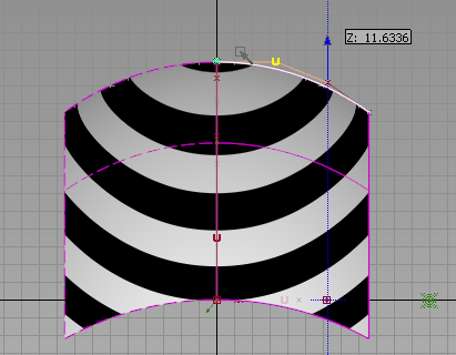
- Pick the second CV from the center (a "U" to indicate the U direction vector, instead of an "x").
- Hold down the key to magnet-snap, and click-drag with the to move the picked CV upward. Move the cursor near the first CV of the same curve, and the picked CV snaps to the same height as that CV.
(If the CV "flies off" to some other point while moving, Edit
Undo with + Z (Windows) or ( + Z (Mac), and try again.)
 - Tumble the view to Perspective with either the ViewCube or the keyboard navigation shortcut.
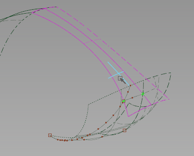
The "zebra stripes" appear continuous as they cross the centerline between the surfaces, indicating that tangency has been achieved.
Construction History updates an object when a source object is modified. Moving the second CV to be in line with the initial CV, and perpendicular to the plane of symmetry provides a tangent condition.
Trim the surfaces
The top surfaces do not match the shape of the top of the vacuum design, but the surface can be trimmed to fit the design without losing its shape.
- Toggle Shade (Fast) ON from the marking menu. This will replace the diagnostic display method.
- Tumble the Perspective view so that the curve drawn on the XY plane from the Top view can be seen underneath the surface.
- Choose Surface EditCreate CurvesOnSurfaceProject
 .
. The prompt line states Select surface(s) or projection vector. Enter X, Y, or Z for axis.
- Drag-select the two top surfaces.
- Before proceeding, type Z on the keyboard and press Return, to change the projection vector to follow that axis.
- Click the Go button in the lower right corner of the view window.
- Select the curve drawn from the Top view onto the XY plane that is visible underneath the shaded surface.
- Click the Project button in the corner of the view.
A curve projects onto the surfaces.
- Choose Surface EditTrimTrim Surface
 .
. - Pick the front surface with the projected curve on it.
- Click a second time on the surface at a point near the centerline.
- Click the Keep button, and view the trim.
- While the Trim tool is still active, pick the back surface.
- Click the outside region of the back surface.
- Click the Discard button.
- Pick Object to end the Trim tool, and tumble around the newly trimmed top surface.
The result looks a lot more like the top surface from the sketch.
- FileSave the model as vacuum_part3.wire.
Use the Object Lister for layer control
Another way to navigate the contents of your scene and manipulate layers is with the Object Lister.
- Choose WindowsObject Lister
 to open the options for the Object Lister window.
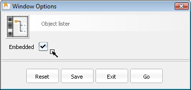
- Check the option for Embedded.
- Click Go to open the Object Lister in the embedded state.
The Object Lister will appear, attached to the left side of the Alias window area. The Embedded option creates a window that does not float above the main window, and can be quickly accessed when needed.
- Click the Show/Hide toggle in the lower right corner of the embedded Object Lister to change the method of access.
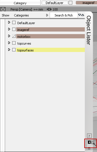
The "double-arrow" toggle
 means the embedded Object Lister will open or close when the mouse cursor passes over it. The "single-arrow and bar" toggle
  means the embedded Object Lister title bar on the right side must be clicked to open or close the window.
 - Choose ShowBy Layer from the menu at the upper left corner of the Object Lister.
The Object Lister organizes your scene based on either modeling layers (By Layer), or in the following order: Canvases, Construction Entities, Group Nodes, followed by all other geometry (By Object). The default is By Layer.
- -click the imageref layer in the Object Lister, and choose Visible from the context menu. -clicking on the visibility toggle box to the left of the layer name will also toggle visibility. Note: The Object Lister layer menu is similar to the Layer Bar drop-down menu, two additional commands: Insert New Layer and Delete Selected Layers. This makes layer creation and management much faster.
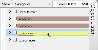
- -click the arrow next to each layer to show or hide the object contents of the layer.
- -click the topcurves layer to make it active for the next modeling step.
- Hide the embedded Object Lister to see the full workspace.
Create the back surface
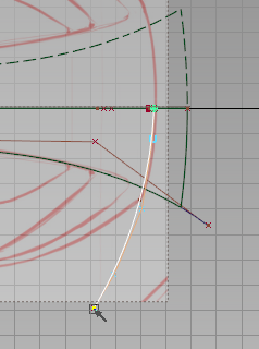
- Click the Left face of the ViewCube to show the left orthographic view.
- Choose CurvesNew CurvesNew Edit Point Curve
 tool, and draw curve along the back edge with -click and drag to place three edit points.
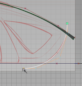
- Pick Nothing to end the curve.
- Switch to the Top view with the ViewCube.
- Using the display marking menu, Toggle Shade OFF.
- -click and drag to start a new edit point curve by the back edge, and press (Windows) or (Mac) to snap this point to the centerline.
- -click and drag to place two more edit points to define the back curve.
- Pick Nothing to end the curve.
- Choose Object EditAlignSymmetry Plane Align
 .
. - Click the new curve near the centerline. It will now maintain a smooth alignment across the symmetry plane.
- Open the embedded Object Lister, and make the topsurfaces layer active.
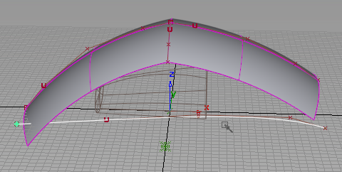
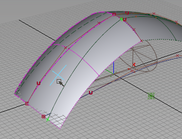
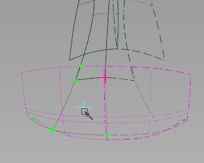
- Choose SurfacesSwept SurfacesRail Surface, and pick the back curve as the generation curve. Note: You may need to set the Rail Surface options back to Single Rail for this to work as expected.
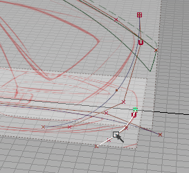
- Pick the back edge curve as the primary rail curve.
With symmetry active for this layer, a symmetric version of the new surface (with dashed edges) is visible as well.
- FileSave the model as vacuum_part3.wire.
Modify the back surface
When you modify the curves of the back surface, the model updates due to active Construction History.
- Choose WindowDisplayTogglesGrid
 .
. This will hide the grid in all views to make further steps easier to see.
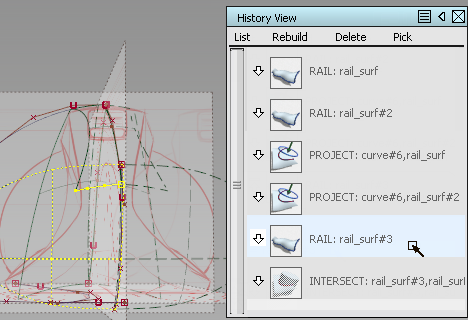
- Choose WindowsInformationHistory View
 .
. This window shows the objects in the scene with Construction History, grouped by the tool that created them.
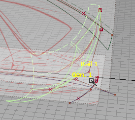
- Click the text of the last RAIL surface.
The back surface highlights in the scene.
- Expand the history components.
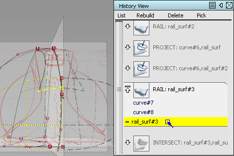
- Click each component to see it highlighted.
- From the History View menu, choose PickConstructors.
The source curves are picked in the scene.
- Close the History View.
- Pick Object and -click the generation curve to unpick it.
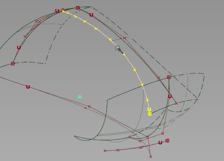
- Choose Curve EditModifyStretch
 .
. This tool modifies the curve with handles, but retains the overall curvature.
- Click the bottom handle and stretch the curve until the surface fully intersects the XY plane.
- Check the intersection in the Perspective view. The image canvas for the Top view will help, since it lies on the XY plane.
- Choose Surface EditCreate CurvesOnSurfaceIntersect
 .
. - Pick the back surface and click Go.
- In the Object Lister, -click the imageref layer and set the state to Pickable.
- Pick Canvas 1 for the intersecting plane, either from within the Object Lister or interactively in the scene.

- Set the imageref layer back to Reference and then toggle the visibility.
Duplicate and project the back curve
To create a region on the back surface to trim, the edge of the top surface can be extended down while maintaining curvature.
- Make the topcurves layer active.
- Choose Curve EditCreateDuplicate Curve
 .
. - Pick the trim edge of the top surface.
A new curve without Construction History is created.
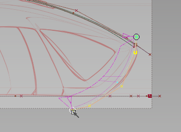
- Choose Object EditExtend
 .
. - Click the new curve, and choose the object named RebuildCurve from the pick chooser.
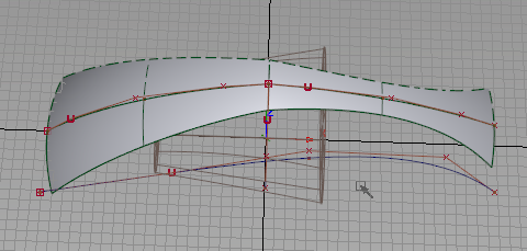
- Drag the Extend manipulator until the curve extends beyond the bottom of the back surface.

The curvature of the original curve is maintained during extension.
- Choose Surface EditCreate CurvesOnSurfaceProject.
- Pick the back surface, and type x to set the projection vector.
- Click Go.
- Pick the extended curve, and click Project.
- Hide the topcurves layer.
Trim the back surfaces
The back surface now has two curves-on-surface, but they do not completely enclose a region for trimming.
- Switch to the Perspective view.
- Choose Surface EditCreate CurvesOnSurfaceIntersect.
- Pick the top surface and click Go.
- Pick the back surface to intersect.
Curves are created on both surfaces.
- Choose Surface EditTrimTrim Surface.
- Pick the top surface, and click the interior region.
- Click the Keep button.
- While the Trim tool is still active, pick the back surface, and click again on the interior region.
- Click the Keep button. All exterior regions are trimmed off.
- Toggle Shade (Fast) the view to see the results.
- FileSave the model as vacuum_part3.wire.