Part designers can now get fast feedback on the manufacturability, cost, and environmental impact summaries of their part as a part develops.
There are now two versions of Autodesk Simulation DFM available.
Autodesk Simulation DFM - add-in
Giving feedback from within your CAD environment, this small, but powerful embedded widget can give feedback as you modify your part.
The 2014 version has expanded the supported CAD platforms to include Inventor 2014, Inventor LT 2014, Creo Parametric v1 & 2, and SolidWorks 2013.
Autodesk Simulation DFM - standalone viewer
The following features have been added to the standalone viewer
- Ribbon interface
- By incorporating a ribbon interface, the functionality of DFM has been enhanced with an easier, more intuitive workflow.
- Material selection
- Material selection has been made easier with the incorporation of a dialog that lists plastic family groups along with some common uses.
- The relative cost and material impact for each family are also displayed graphically.
- This list can be sorted based on the part application, or physical attributes such as impact resistance.
- Pull Direction
- The previous release would only allow for a pull direction in one of the major axes that the part was modelled in. The pull direction can now be set to any direction. Simulation DFM can check the part based on the orientation of the part within the mold that you have specified. Draft angles and undercuts can be allowed for at design stage.
- To specify a pull direction, do the following.
- With the model loaded into DFM, click
 ()
() - Click on the surface of the model and a pull direction is place at right angles to the surface.
- With the model loaded into DFM, click
-
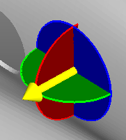
The pull direction can be further modified in two ways.
- Manually
- Clicking on the yellow arrow and dragging it to the desired direction.
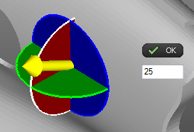
- Specified
- Select a plane of rotation, the plane is highlighted and a text box appears.
- Enter the angle of rotation in degrees. Click OK.
-
-
Repeat for the other planes as required.