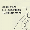
The format for hole notes is controlled by the hole note's associated dimension style. Before you begin a drawing, define a dimension style with a hole note definition for each hole type.
Set up hole note format in the dimension style
- Select
Manage tab
 Styles and Standards panel
 Styles Editor
to open the Style and Standard Editor. Expand the Dimension style category, and then double-click a dimension style.
 - In the Dimension Style window, click New to create a style, if needed.
- In the New Style Name dialog box, accept the default "Copy of Default (xxx)" or enter a new name.
- Select the Add to Standard check box so the new style is available to all documents that use the standard. Click OK.
- Click the Notes/Leaders tab to view the hole settings.
- Select the hole and thread type.
- In the Options box:
- Clear the check mark from Use Default to edit settings.
- If available, select Tap Drill to apply settings to selected hole and thread types.
- Select Part Units to use model units for hole notes.
- Click Precision and Tolerance to specify preferences for precision and tolerance parameters in the Precision and Tolerance dialog box.
- Click Apply to All to apply selected settings to all hole and thread types, including settings in the Precision and Tolerance dialog box.
- Click Values and Symbols buttons to add their variable names in the edit box.
- In the General Settings box:
- Click Edit Quantity Note to set contents of quantity notes in the dialog box.
- Click the arrow to select a Leader Style. If appropriate, click Edit Leader Style to close the dimension style and change leader style characteristics.
- Select the check box to set text justification.
- Click the arrow to select leader text orientation.
- Click the arrow to select leader text alignment relative to the landing line.
- In Thread Note Settings, select Custom Designation to apply the custom thread designation field from the Thread.xls spreadsheet instead of the default note.
- Select another hole and thread type and define its settings. Repeat for each hole type in the drawing.
Note: Save the settings before you close the dialog box.
Edit format for a selected hole note
- In the drawing view, right-click a hole note, and select Edit Hole Note or double-click a hole note. In the Edit Hole Note dialog box, Hole Type, and Thread Type cannot be edited.
- In the Options box:
- Clear the check mark from Use Default to edit settings.
- If available, select Tap Drill to apply settings to the selected hole and thread type.
- Select Part Units to use model units for the hole note.
- Click Precision and Tolerance to specify preferences for precision and tolerance parameters in the Precision and Tolerance dialog box.
- Click Edit Quantity Note to change settings in the Quantity Note dialog box.
- In the edit box, click and Backspace to remove existing values.
- Click Values and Symbols buttons to add their variable names in the edit box.
- Click OK to apply the new settings to the selected hole note.