An existing joint can sometimes be modified without being deleted. You can modify some of the original creation parameters, depending on the joint type and properties.
The following rules apply to modifying joints:
- To modify standard joints created with Automatically Convert Constraints to Standard Joints, modify the constraints between the two components and the software automatically updates the joints.
- You can never change the type of joint to a type in another category.
For example, you cannot change a revolution joint to a 2D contact joint because they are in different categories.
- If the standard joint was created with Convert Assembly Constraints, clicking Edit opens the Convert Assembly Constraints dialog box, where you can reselect mate constraints.
- For joints created with Insert Joint, clicking Edit opens the Modify Joint dialog box, where you can change the
joint coordinate system
.
You can only select entities that belong to the components that originally composed the joint.
Note: You cannot change the order of component selection, that is, change parent component to child component and child component to parent component. - For rolling, sliding, 2D contact, and force joints, you can also change certain other properties as follows:
- For belt joints, you can modify belt type (that is, straight or crossed).
- For screw joints, you can modify pitch or create a cylindrical joint.
- For Rolling: cylinder in cylinder, Rolling: cylinder on cylinder, and Rolling: cylinder on plane joints, you can change from 1 constraint to 2 or from 2 constraints to 1.
- In the Dynamic Simulation browser, right-click the joint you want to modify and select Edit.
The dialog box associated to the joint creation method opens. The allowable edit controls are enabled.
- On the dialog box, make your changes.
As long as the modification is not validated, you can come back to a choice by clicking the corresponding icon.
- Click OK.
The program validates the joint, applies your changes, and closes the dialog box.
 Show Me how to edit the initial position of a joint
Example: Modifying a revolution joint to simulate a torsion spring?

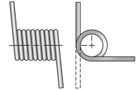
The revolution joint has properties that can simulate a spring condition. A torsion spring can be made using any revolution joint having degrees of freedom.
- Right click the Revolution joint and select Properties to see the Properties dialog box.
- Select the appropriate DOF tab.
- Click the Edit joint torque icon

- Check Enable joint torque and define the Spring parameters: Free position and Elastic stiffness. The free position is related to the initial position in the degree of freedom.
- You can also define a damping value to have a visco-elastic spring.
 Show Me how to edit a joint