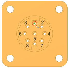
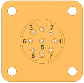
Add pins to a connector already present in Enclosure_Assembly_basics.iam.
- In the assembly browser, double-click the part named 360124 to open the part for edit.
- In the model browser, delete work points 1 through 9. You re-create these points in the next steps.
- On the Model tab, Harness panel, click Place Pin.

- Rotate and zoom the view to see the part as shown. Turn Visibility off for any parts that obstruct your view.
- In the graphics window, move the cursor over the part geometry to highlight valid points for your selection. Highlight the circular edge shown, and then click to select the center point.

- On the Place Pin dialog box, use the default pin name of 1.
- Click Harness Properties
 to display the Connector Pin Properties dialog box.
 - Click the Custom tab to view where common properties are added. Without changing the properties, click Cancel.
- Click the green check mark. The work point that represents pin 1 appears.
- Repeat the necessary steps to create pins 2 through 9.

- Right-click, and select Done to exit the Place Pin command.
Save your file.