In some cases, it is appropriate that certain parts move as a rigid body and a joint is not required. As far as the movement of these parts is concerned, the welded body functions like a subassembly moving in a constraint chain within a parent assembly. Similarly, at other times, components making up a welded group need degrees of freedom for movement within the simulation. Such is the case with the welded group in the Saw model.
Create a 2D contact
- In the browser, expand Mobile Groups.
- Right-click the Follower Roller, and click Retain DOF. The roller retains its motion characteristics.
- In the graphics region, click and drag the Follower away from the Cam crank assembly.
- On the ribbon, click
Dynamic Simulation tab
 Joint panel
 Insert Joint
and from the list, select 2D Contact.
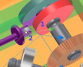
 - Select the Cam profile edge (1).

- Select circular sketch (2) on the roller component.
- Click Apply. As you can see, sketch geometry can be used to help define the simulation.
- Drag the Follower until the roller contacts the cam. Notice it does not penetrate. The 2D contact established a mechanical relationship between the two components.
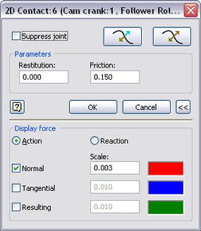
- Set the properties for the 2D contact and display the force vector. In the browser, right-click the 2D Contact joint and click Properties.

- Set the Restitution values to 0.0.
- Expand the dialog box to access the lower section. Check the Normal box and set the Scale to 0.003.