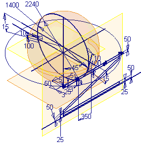
You use a supplied sample model, which is the completed skeleton part, to derive the required frame parts. Examine this part before you create the assembly.
- Set your active project to tutorial_files.
- Open SkeletonBase.ipt.
The part contains sketches, work features, and construction surfaces that define the basic geometry of a support frame for a spherical container. Skeleton models are suitable for static models, such as frames and other fabricated assemblies. The initial jumble of geometry may look a bit confusing, so we will look at the individual sketches and other geometry in the part.

- In the Model browser, drag the End of Part marker and drop it just below the STRAP SURFACE node.
- On the ribbon, click
View tab
 Navigate panel
 View Face
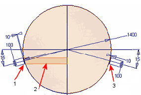
, and then click CIRC STRAP SKETCH in the Model browser.
1 - Strap Surface Profile
2 - Strap Surface
3 - Strap Body Profile
The spherical construction surface is the key feature in the part. The diameter of the sphere drives the other geometry in this skeleton, and consequently drives the size of parts derived from this skeleton.
The shared strap sketch contains two related profiles:
- A body profile that you will use to revolve a strap encircling the sphere.
- A surface profile used to create the strap surface feature. This feature is used as a termination surface for supports between the strap and the external frame surrounding the sphere. Further information is provided when the supports are created later in this tutorial.
Note: The two sketch profiles are linked by parameter values. - Drag the End of Part marker below the Work Plane-BOTT of Frame node in the Model browser, and examine the location of the three work planes.
The three work planes below STRAP SURFACE define the vertical extents of the exterior frame. The BOTT of Frame work plane is used as the termination face for the vertical legs of the frame. The sketch for the vertical leg is on the TOP of Frame work plane.
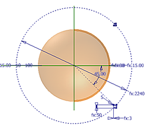
- Drag the End of Part marker below the VERTICAL LEGS SKETCH node in the Model browser. Use the View Face command to reorient your view like the following image.

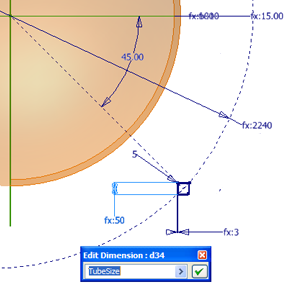
The sketch contains a profile for the square tubing leg. The 2240-mm dimension is related to the diameter of the sphere. The size and thickness of the tubing is controlled with user-defined parameters. The following image shows the size of the tubing controlled by the TubeSize user parameter. The user-defined parameters are exported, and thus can be referenced by any of the parts derived from the skeleton part.

- Drag the End of Part marker to the bottom of the Model browser. Examine the remaining sketches. Note that all sketches are related through projected geometry, work feature definition, or parameters. The sphere diameter drives all the critical dimensions of the frame.