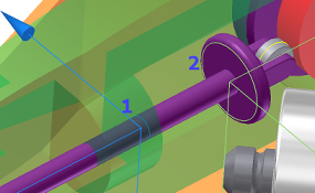
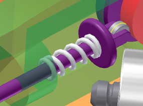
The Follower is designed to slide through a portion of the Guide component. However, to hold the Follower Roller against the Cam, specify a spring between the Follower and Guide components. Dynamic Simulation has a joint for doing that and more, the Spring/Damper/Jack joint.
Define gravity
- On the ribbon, click
Dynamic Simulation tab
 Joint panel
 Insert Joint
and in the list, select Spring / Damper / Jack joint.
 - On the Guide component, select the hole profile where the follower passes through the Guide (1).
- Select the edge profile where the spring contacts the follower.

The result is a spring joint in the browser and a graphic representation of a spring. The representation is deformable and has action-reaction forces, but does not have mass.

- In the browser, in the Force Joints folder, right-click the Spring joint and click Properties.
- In the main section of the dialog box, set:
- Stiffness = 2.500 N/mm
- Free Length = 42 mm
Expand the dialog box and set:
- Radius = 5.2 mm
- Turns = 10
- Wire Radius = .800 mm
- Click OK. The spring properties and graphical display update.
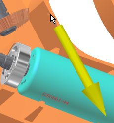
- In the browser, in the External Loads folder, right-click Gravity and click Define Gravity. Alternatively, you can double-click the Gravity node. If necessary, clear the Suppress check box.
- Select the Case edge, as shown in the following image, to specify a vector for gravity.Click OK
