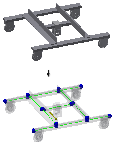
We are ready to enter the Frame Analysis environment.
- On the ribbon, click Environments tab
 Begin panel
 Frame Analysis
 .
.Initially, there are only three commands enabled: Create Simulation, Frame Analysis Settings, and Finish Frame Analysis. For now, create a simulation and review the settings in the next step.
- On the Manage panel, click the Create Simulation
 command. The Create New Simulation dialog box opens.
You can use the dialog box settings to specify a unique name, simulation type, and other simulation parameters.
There are two types of Frame Analysis.
- Static Analysis evaluates structural loading conditions.
- Modal Analysis evaluates natural frequency modes.
Note: On the Model State tab, you specify the Design View, Positional, and Level of Detail to use for the simulation. Also, you can specify the iAssembly member to be associated with the simulation. The settings can be different for each simulation. - Click OK to accept the default settings for this simulation.
The Inventor model is automatically converted into idealized nodes and beams, and a simulation is created. A gravity symbol also displays.

The browser populates with a hierarchical structure of the assembly and analysis-related folders.
Most of the commands in the ribbon panels are now enabled for use. Disabled commands enable after you run the simulation.