|
|
Use the Cut command to remove material from a sheet metal face, or to cut material across a sheet metal bend.
|
Create a simple sheet metal cut
To begin, sketch a profile that represents the shape of the material you want to remove.
|
|
- On the ribbon, click
Sheet Metal tab
 Modify panel
 Cut
.
Cut
. If there is only one profile in the sketch, it is automatically highlighted.
- If there are multiple profiles, click
Profile
, and then select the profile for the cut.
- Under Extents, click the down arrow and select the method to terminate the extrusion.
- For Distance, click the down arrow beside Thickness and select the method to determine the thickness. Click a direction for the cut.
- For To Next, click a direction button to specify the direction for the cut.
- For To, click the face on which to terminate the cut. If appropriate, select the check box to indicate that the cut does not extend beyond the selected face.
- For From To, click the beginning and ending faces for the cut.
- For All, click the direction of the cut.
- Click OK.
Note: If your sketched profile overlaps a bend, the Cut command removes material based on the extents and direction defined. Use the Cut Across Bend option to create a through or partial-depth cut that wraps around the bend.
|
Create a cut across a sheet metal bend
|
|
- On the ribbon, click
Sheet Metal tab
 Modify panel
 Cut
.
Cut
. If there is only one profile in the sketch, it is automatically highlighted.
- If there are multiple profiles, click
Profile
and then select the profile for the cut.
- Check Cut Across Bend.
- Accept the Thickness parameter as the cut depth for through cuts or specify a partial depth cut as a percentage of the Thickness parameter or by entering a precise depth value.
- Click OK.
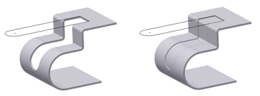
Note: The following illustration (on the left) shows a simple cut across multiple bends with the distance value set equal to the Thickness parameter. Using the same simple sketch, the illustration on the right shows the same cut across bend with the distance set to Thickness/2. The sketch was set to visible on both examples.
|

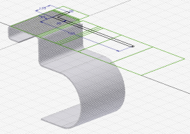
Tip: When creating a profile sketch that is used to create a cut feature that cuts across bends, it is useful to have unfolded geometry projected in your sketch. After you start your sketch by selecting a planar face, use the Project Flat Pattern sketch command (located with the Project Geometry and Project Cut Edges commands) to select faces adjacent to your originally selected sketch face. This command projects the flattened face along with bend lines which can be used for dimensioning your sketch. Finally, you may find that using the sketch Slice Graphics option helps you by removing folded model geometry from the plane of your sketch.
Note: You can use a
shared sketch
as a profile. In the browser, click the plus sign (+) beside the feature that contains the sketch you want to use, right-click the sketch icon, and then select Share Sketch.


 Show Me how to create a cut across a bend