 |
 |
 |
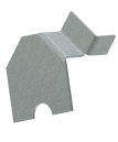
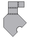
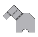
Once a flat pattern is created, it can be reoriented by causing any straight feature edge, virtual line between two vertices or line of tangency to align vertically or horizontally. The pattern can also be flipped front to back as required.
Reorient the default flat pattern
- Create a Sheet Metal part.
- On the ribbon, click
Sheet Metal tab
 Flat Pattern panel
 Create Flat Pattern
.
 - With the flat pattern active, right-click the Flat Pattern node in the browser.
- Select Edit Flat Pattern Definition from the context menu.
- Choose either Align Horizontal or Align Vertical.
- Pick a straight edge or two points on the flat pattern.
- Click Flip (if required).
- Click Save.
- Click OK to close the dialog box.
The default flat pattern reorients relative to the edge or line that is aligned either horizontally or vertically.
Add a named flat pattern orientation
- On the ribbon, click
Sheet Metal tab
 Flat Pattern panel
 Create Flat Pattern
.
 - With the flat pattern active, right-click the Flat Pattern node in the browser.
- Select Edit Flat Pattern Definition from the context menu.
- Right-click on Default (or another named orientation) in the Orientations table and select New from the context menu.
- Enter a name in the displayed Orientation Name dialog box and click OK.
- Choose either Align Horizontal or Align Vertical.
- Activate the selection command.
- Pick a straight edge or two points on the flat pattern.
- Click Flip (if required).
- Click Save.
- Select the newly created named orientation from the Active Flat Pattern Orientation drop-down list and click Apply.
- Click OK to close the dialog box.
Delete a named flat pattern orientation
- On the ribbon, click
Sheet Metal tab
 Flat Pattern panel
 Create Flat Pattern
.
 - Click Create Flat Pattern on the Flat Patten panel of the Sheet Metal tab.
- Select Edit Flat Pattern Definition from the context menu.
- Right-click on a named orientation in the Orientations table and select Delete from the context menu.
- Click OK to close the dialog box.
Rename a flat pattern orientation
- On the ribbon, click
Sheet Metal tab
 Flat Pattern panel
 Create Flat Pattern
.
 - With the flat pattern active, right-click the Flat Pattern node in the browser.
- Select Edit Flat Pattern Definition from the context menu.
- Right-click on a named orientation in the Orientations table and select Rename from the context menu.
- Click Save.
- Optionally, select the newly renamed orientation from the Active Flat Pattern Orientation drop-down list and click Apply.
- Click OK to close the dialog box.
Tip: While editing the orientation of a flat pattern, an alignment indicator consisting of red and green arrows displays. The red arrow indicates the horizontal (X-axis). The green arrow indicates the vertical (Y-axis). When the Align Horizontal option is selected, the red arrow in the display is longer than the green arrow. When the Align Vertical option is selected the green arrow in the display is longer than the red arrow. Careful attention to these arrows assists you as you select alternate alignments and flip directions.
Note: Take care when creating drawings of flat patterns. Bend and punch notes which indicate a direction do so relative to the flat pattern view shown in the model. Up is towards you relative to the shown (or named) view and Down is away from you relative to the shown (or named) view.