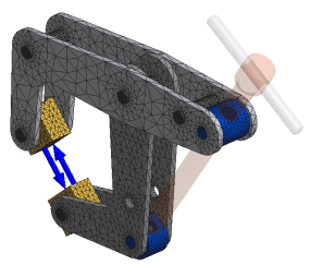
Before running the simulation, view the mesh to make sure that any areas needing a different mesh setting from the default are cared for. First, we will specify the mesh settings.
- In the Mesh panel, click Mesh Settings
 . Alternatively, right-click the Mesh folder and click Mesh Settings.
 - Set Maximum Turn Angle = 30 to capture round areas of the geometry.
- Check Create Curved Mesh Elements.
- If not already checked, check Use part based measure for assembly mesh.
This option uses the part size as mesh criteria, as opposed to a single size for all parts.
- Click OK.
- Having specified the mesh settings, you preview the mesh by clicking the Mesh View
 command. The results are a mesh overlay on every part participating in the simulation.
Note: If areas of the model need a finer or more coarse mesh, add local mesh controls. Local mesh controls are covered in another tutorial.