AutoDrop enhances drag-and-drop techniques with functional design automation. AutoDrop automatically checks geometry for placement and sizing based on the content family characteristics. Geometry capable of supporting content within the selected family is highlighted and AutoDrop previews recommended size and placement. As you move the cursor past different supported geometry, AutoDrop dynamically updates the preview until you make a selection. Once selected, use the available commands to edit or accept the size.
For example, you can drag a Nut family to the bolt in an assembly. AutoDrop finds the appropriate nut, inserts it, and mates it in the context of the assembly. This feature eliminates the need to browse or search for the appropriate part and size.
You can place the following components using AutoDrop:
- Bolts (except bolts included in the Other category)
- Nuts
- Washers (except washers - Balls)
- Clevis Pins
- Bearings
- Circlips
Before placement, you can resize the part using a grip arrow. Tooltips provide you with information about the dimensions.
The grip is displayed only if the part size is uncertain. For example, if you select a target edge for a bolt placement and there is only one available bolt length for the given diameter, then no grip is shown. If there are more bolts with the same diameter and different length, then the length grip is displayed. For nuts, washers and circlips there is no grip, as the diameter defines individual family members. For pins and bolts, a grip for length is displayed if there are more available lengths. For bearings, a grip is displayed to enable a selection of different bearing sizes. If the bearing is placed on a hub, use the grip to specify the inner bearing diameter. If the bearing is placed on a shaft, use the grip to specify the outer bearing diameter.
When you pause the cursor on a target for a moment, AutoDrop tries to update the part size. Before the update, the cursor is a question mark. After the update, a tooltip displays to specify the part size. The cursor is either a check mark, indicating that a corresponding part size was found, or a cross mark, indicating that there was a problem finding a corresponding size. In this case, the preview and tooltip color changes to red.
AutoDrop preview
Once started, AutoDrop displays a facet preview for the given family. The preview uses either the last dropped member of the family, or the size of the template model.
To generate the facet previews of individual members, AutoDrop temporarily opens and modifies the template part file and reads the facet information. For reuse, AutoDrop stores this facet information in a temporary folder - Documents and Settings\username\Local Settings\Temp\Inventor Facets.
If you drop a part, the information about which member of the family was dropped last time is kept in the local defaults folder, LastDroppedPart.ini file - Documents and Settings\username\Application Data\Autodesk\Autodesk Inventor [ver]\DesignAccelerator\Defaults\LastDroppedPart.ini.
AutoDrop cursor and tooltips
The cursor shape differs for individual Content Center categories and target geometries. Generally, the cursor shape contains a geometry icon ( ![]() )and a symbol (
)and a symbol (![]() ). The geometry icon specifies which target geometry to select for the placement. (Examples: shaft circular edge, hollow circular edge, cylindrical face, conical face, planar face, and so on.) The symbol highlights whether the facet preview was successfully updated for the target geometry.
). The geometry icon specifies which target geometry to select for the placement. (Examples: shaft circular edge, hollow circular edge, cylindrical face, conical face, planar face, and so on.) The symbol highlights whether the facet preview was successfully updated for the target geometry.
| Symbol | Meaning | |
|---|---|---|
|
|
question mark |
Either no target geometry is preselected or selected, or the preview size is not updated yet. |
|
|
check mark |
Target geometry is preselected or selected and the updated member fits the target geometry. |
|
|
cross mark |
Target geometry is preselected or selected and the updated member fails to fit the target geometry. |
The status bar tip specifies which target geometry to select. Also, whenever the preview size is changed, the tooltip displays the current member information.
Preselect the target geometry
When the cursor is placed on target geometry, the facet preview is immediately positioned according to the target. After pausing a cursor, the facet preview size is also updated to the best fit. The cursor is updated to highlight whether the member size fits the target or not.
Whenever the facet size changes according to the preselected target, the tooltip displays the member size information.
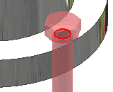
If AutoDrop fails to find a member that fits the target, both the facet preview and the tooltip is highlighted in red. However, you can place the member to the selected target.
Select the target geometry
If you select target geometry, which does not fully constrain the component position, the preview position is limited with the selection. For example, while dropping a bolt, you can select a circular edge, which fully constrains the bolt diameter and placement with a single selection. You can also select a cylindrical face. Then, the bolt diameter is updated to fit the face diameter. The preview can be dragged only along the target axis. Planar faces normal to the cylinder are allowed for subsequent selection.

During a target selection process, you can also cancel the selection of the target. For example you can unselect a cylindrical face to follow, and select a circular edge. Or, you can use the context menu to insert the component with the existing constraints (for example, to insert a bolt constrained along the hole axis).
AutoDrop toolbar
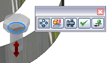
If you fully specify the target geometry, AutoDrop updates the preview size (if it was not up-to-date already) and displays AutoDrop toolbar with insertion commands. Depending on the particular Content Center family, the preview can display a grip to specify a bolt length, for example.
A toolbar differs according to the inserted component. In the following image, see the toolbar when inserting a bolt to the patterned hole. For complete overview of toolbar commands, see the AutoDrop help topic.

AutoDrop context menu
Insert the selected member from Content Center without the completed target geometry selection using the context menu commands:
| Symbol | Meaning | |
|---|---|---|
|
|
Apply |
This command finishes the current insertion and AutoDrop continues with the given family. You can insert several sizes during one command. The default member is always the last one dropped. |
|
|
Done |
Click to finish the current insertion and stop AutoDrop. |
|
|
Flip |
Flips the component side used for insertion. Available only for specific families of bearings. |
|
|
Change size |
Select to insert and mate the member. Opens the Content Center Family dialog box where you can select a member of the needed size. Click this command to stop AutoDrop (the same as Done). |
|
|
Bolted Connection |
Opens the Bolted Connection Generator using the selected bolt and the placement (either By hole or Concentric, depending on the target geometry). Click this command to stop AutoDrop (the same as Done). This command is available in AutoDrop only for specific bolt categories that the Bolted Connection Component Generator supports. Also, either select or preselect an appropriate target. |
|
|
Cancel [ESC] |
Cancels the AutoDrop operation. |
3D grips for AutoDrop
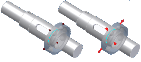
If there are more sizes available for the specified target, the preview shows a size grip. Drag the grip to select the proper member. The facet preview updates only when the facet information is already cached. Otherwise, only the grip position and the tooltip info is changed while dragging the grip. When the drag completes, the preview updates. See the following image.
Since the facet information is not cached yet, the first two size changes during grip drag change only the grip position and the tooltip information. Release the mouse to rebuild the facet and update the preview.
With bearings, one of the bearing diameters is determined with the target, and the other is driven with the grip. The diameter grip behaves the same as with Design Accelerators.

Double-click the grip to view a menu with available sizes for a quick selection.
What if several family members are available in AutoDrop?
If you click Apply ![]() or Done
or Done ![]() and there are several family members that fit the existing criteria, AutoDrop displays a table to specify the member to insert. A table can display for several available materials including, thread types, bearing widths, and so on.
and there are several family members that fit the existing criteria, AutoDrop displays a table to specify the member to insert. A table can display for several available materials including, thread types, bearing widths, and so on.
The contents of the table differs depending on the workflow. For example, if you drop a bolt and click Apply or Done, the table includes different bolt lengths. It is because you could not use AutoDrop grip to set the bolt length. But if you click Apply or Done from the AutoDrop toolbar, the bolt length is expected to be correct, specified through the length grip. In this case, the table is displayed only if there are still several members available with the same diameter and length.
Integration of AutoDrop and Design Accelerator component generator commands
Access the Bolted Connection Generator:
You can access the Bolted Connection Generator directly from an AutoDrop bolt. It facilitates the placement of additional components which require browsing, drag, selection, and resizing to build the appropriate connection.
Once the target geometry for the bolt is selected, the Bolted Connection Generator is available on the AutoDrop dialog box.
While dragging the bolt, highlight the target geometry, right-click, and select Bolted Connection Generator ![]() from the context menu.
from the context menu.
Bolted Connection Generator is accessible only for bolts that are supported with the Bolted Connection Generator.
Selected family from Content Center does not contain part size fitting to the selected geometry

When you use AutoDrop for a family that does not contain the appropriate dimension according to the selected target geometry, the part preview and the tooltip turn red. For example, you try to insert a bolt to a hole with the 0.25-inches diameter and the selected family contains the smallest component of 1-inch diameter. However, you can insert such a component.
To change the component size, right-click and select Change size from the context menu.