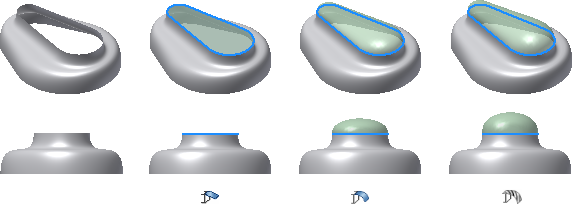
The boundary patch feature generates a planar or 3D surface from a closed 2D sketch, a closed boundary, or a mixture of both. The patches default to contact (G0), but can have edge conditions of tangent (G1) or smooth (G2) applied to each nonsketch edge in the Condition list.
You can also enable feature preview to view the results before creating the patch.
The boundary can be defined as follows:
Edge Selection You select edges which define a closed loop. Because continuous edges must have the same edge condition, all selected surface edges that are tangent or continuous with the previous item are merged. Chaining stops at the first non-tangent selection, even if they are stitched into a single surface.

The OK command is enabled once a closed loop has been defined so that you can select additional loops. By selecting additional loops, you can define inner and outer loops to create islands in the surface. If a planar region is selected, the selection of additional loops is not allowed.
Edge conditions can be applied to each nonsketch edge in the selection set for a loop. By default, all boundary segments are G0. You can apply G1 or G2 conditions to any nonsketch edges only if they have a single adjacent face. Boundary edges can include a mixture of G0, G1, and G2 conditions.
