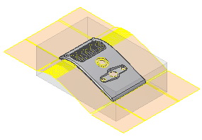
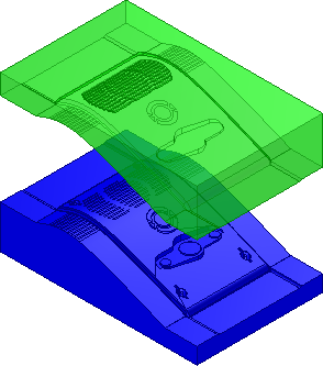
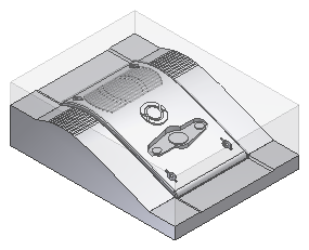
In this section, you return to the mold assembly and automatically create the patching and runoff surfaces on the modified model geometry. To complete the section you create the core and cavity based on the patching and runoff surfaces.
- Activate the mold assembly.
- On the Quick Access toolbar, click Local Update
 .
. - On the ribbon, click
Core/Cavity tab
 Parting Design panel
 Create Patching Surface
 .Note: Click Core/Cavity in the Mold Layout panel to activate the Core/Cavity tab. You can also double-click the plastic part in the Mold Design browser.
 - On the Create Patching Surface dialog box, select Auto Detect
 to create the internal patches automatically. Now that the model has been modified the system automatically detects all the surfaces for the Grill, as shown in the following image.
- Click OK. The model appears as shown in the following image.

- On the ribbon, click Core/Cavity tab
 Parting Design panel
  Create Runoff Surface
  .
. - On the Create Runoff Surface dialog box, select Auto Detect
 to create the runoff surfaces automatically.
 - Click OK to generate the runoff surfaces. The model appears as shown in the following image.

- On the ribbon, click
Core/Cavity tab
 Parting Design panel
 Generate Core and Cavity
 .
. - Click Preview/Diagnose to perform parting diagnostics and enable the preview controls.
- Use the Body Separation slider in the Preview tab to examine the core and cavity before creation as shown in the following image.
 Note: The Parting Diagnostics tab report does not indicate any serious errors.
 - Click OK to generate the core and cavity. The bodies are generated as shown in the following image.
- Optionally, if Prompt for file names is enabled, click OK in the File Naming dialog box. The core and cavity generates with the default settings.

- Save the file.