Grill features are used to create vents or openings on the thin walls of a part to provide air flow for internal components.
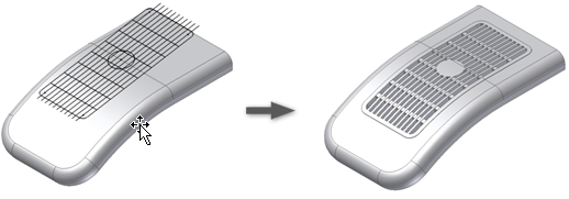
Grill features are created by projecting the patterns of one or more 2D sketches on the surface of the part.
The patterns that are used to define the Grill geometry are:
- Boundary: Must be a closed sketch. It limits the extent of the grill. Often the boundary is raised at an offset of the part surface.
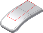
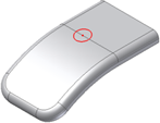
- Island: An area filled with material, usually at the center of the grill. The island often has the same thickness as the shell. It must be a closed sketch.
- Ribs: one pattern that fills the grill area. The external faces of the ribs are flush or slightly recessed relative to the boundary external face.
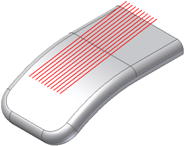
- Spars: A secondary pattern, usually added to improve the stiffness of the ribs.
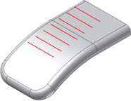
The boundary external contour projection (plus a 10-percent tolerance band around the external contour) must remain entirely within the part surface. No material gaps (holes) are allowed inside the boundary projection. Examples are shown in the following images:
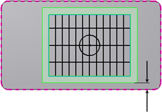 |
Grill ok. The external contour of the Grill boundary projection remains within the target body with a 10-percent tolerance. |
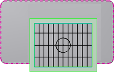 |
Grill did not compute. The external contour of the Grill boundary projection is not entirely included within the target body. |
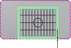 |
Grill does not compute. The external contour of the Grill boundary projection is too close to the margin of the target body (the distance tolerance is below the 10-percent threshold). |
The boundary sketch is the only mandatory element when building a Grill. The area of the openings of a Grill feature is reported in the Flow area section of the dialog box and in a Reference parameter. The flow area does not consider the optional draft angles.