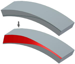
Draft is a taper that you apply to specified faces of a feature. Use Draft to cant one or more faces on a part so that you can retrieve it from a mold. When designing features for molded or cast parts, you can apply draft by specifying a positive or negative taper angle for an extrusion or sweep. To add draft to an existing feature or individual faces, use the Face Draft command.
When you apply draft to a face, the relationship between the pull direction and the fixed edge, face, or plane determines the result of the operation.
You select edges or axes to specify the pull direction (of the mold from the part) and the angle of the draft. The draft angle is calculated from a fixed edge (plus any tangent edges), one or more contiguous edges, or a fixed plane.
Draft applied from selected faces or edges
You can select a single face or multiple contiguous edges per face.
The first selection specifies a single face and a single fixed edge.
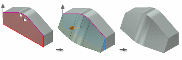
To draft about a chain of faces, continue to select individual edges on the face. Optionally, to cancel the selection, press Ctrl+click an edge or face.
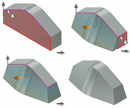
This example shows a split face. If you select a part face near the edge formed by the split, it selects all tangent contiguous faces. That selection also specifies the edge formed by the split as the fixed edge.
Draft applied from fixed plane
You can select a face or work plane to specify both the fixed plane and the pull direction. The default for the pull is normal to the fixed plane, but you can flip it. The fixed plane becomes the pivot for the draft.
These examples show the effects of several types of fixed planes.
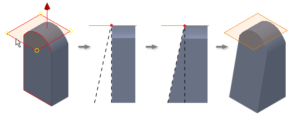
Top face fixed
The fixed top face sets an upward pull direction. All side faces are drafted, adding material below the fixed plane.

In the following example, the fixed work plane is tangent with the curved face. The selected face pivots at the fixed plane, adding material to the model.
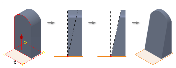
Bottom face fixed
The pull direction is set in an upward direction from the fixed bottom face. All sides are drafted, removing material above the fixed plane.

In the following example, the bottom face is fixed and the pull direction set in an upward direction. Material is removed in the pull direction, using the bottom face as the pivot.
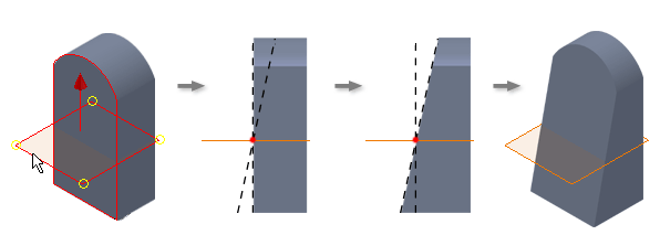
Work plane fixed
An upward pull direction is set from the fixed work plane. The draft angle adds material below the fixed plane and removes it in the pull direction.

In the following example, a work plane is the fixed plane. Material is removed in the pull direction above the fixed plane and added below the fixed plane.
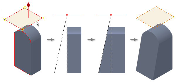
Offset plane fixed
An upward pull direction is set from the fixed offset work plane. The draft angle adds material below the fixed plane, with the angle originating at the intersection of the face with the fixed plane.

In the following example, the offset work plane is selected as the fixed plane. The selected face pivots at the fixed plane, adding material to the model.
Draft applied using parting line
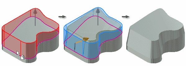
You can select a 2d sketch or a 3d sketch to define the parting line. The draft is applied above and below the selected geometry. All faces that intersect the parting line are selected to be included in the draft.
Draft applies to all faces that intersect the parting line. You can apply a different draft angle above and below the parting line.
