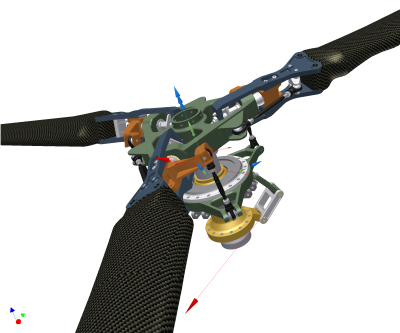
To simulate the dynamic motion of an assembly, define mechanical joints between the parts and add forces (internal, external, or both) on the parts. The assembly is now a mechanism. Joints can be created in three ways:
- Through the Automatically Convert Constraints to Standard Joints command, on by default, in the Dynamic Simulation Settings dialog box. The software automatically converts eligible assembly constraints into standard joints.
Spur Gear sets created by Design Accelerator have rolling joints created automatically. The helix angle, pressure angle, and efficiency parameters are replicated in Dynamic Simulation. The Gear set must be set to flexible to take advantage of automatic constraint conversion.
Automatically created joints can be edited to modify the origin and frame vectors.
- Use the Insert Joint dialog box to insert joints.
- Use the Convert Assembly Constraints command to convert Autodesk Inventor assembly constraints into standard joints manually, one joint at a time.Note: If the Automatically Convert Constraints to Standard Joints command is active, you can only use the Insert Joint dialog box to insert Spatial standard joints.
Modifying assemblies for easier simulation
To make simulation faster and more robust, make the following changes to the assembly either before or after adding joints and forces:
- Carefully consider the assembly and the purpose of the simulation.
- Determine which assembly components are essential to the simulation.
- Simplify the assembly as much as possible.Note: Change a copy of the assembly so that you do not lose design information.
- Isolate the assembly you want to study.
For example, if you want to study the arms of an excavator, do not work directly on the complete assembly. Copy the complete assembly and delete the unnecessary parts. It makes the model easier to build and manage, and improves global performance.
- Create subassemblies of parts that move as single rigid bodies.
For example, an assembly can have a series of bolts that function only to keep two components in contact and motionless with respect to one another. Create a subassembly that contains the two components and the bolts. You can use the demote feature to help you do it.
- Isolate the assembly you want to study.
- Isolate the components of interest and any other components that appreciably affect the simulation.
To determine how much is an appreciable effect, consider the magnitude and tolerances of the results you need.
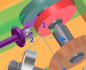
- Before adding a 2D Contact joint, ensure that the components whose edges/profiles are being used as input, have their normals pointing outward (2) away from the joint and are not penetrating or intersecting (1) one another.

The workings of Dynamic Simulation
The following is basic information about dynamic simulation in Inventor, how it works, and what model conditions affect.
- Dynamic Simulation operates only with Autodesk Inventor assembly files (.iam).
- Dynamic Simulation uses the physical properties associated with each part, that is, mass, inertia matrix, and position of the mass center.
- There can be suppressed or inactive parts in the Dynamic Simulation browser, but they are idle and cannot be used for a simulation.
- The origin of the assembly is taken to be the origin of the assembly coordinate system. The principal planes define the X, Y, and Z axes of this coordinate system. It is placed onto the Grounded group. Click the Grounded node in the browser to see which parts are considered to be without degrees of freedom.
- By default, when opening an assembly file, assembly constraints converts to standard joints between parts. Standard joints are not created if there are no assembly constraints between the parts or Automatically Convert Constraints to Standard Joints was disabled.
- A non-flexible subassembly is treated as a single, rigid body. Parts are always rigid bodies. It is not possible to define mechanical joints between the parts of a subassembly that is not flexible.
- Since the parts are rigid and there is no play in the joints, mechanisms can be over constrained. For example, if you specify a joint that constrains a degree of freedom that is already constrained by an existing joint, the mechanism is over constrained.
- The Color Mobile Groups command assigns predefined color overrides to all members of a mobile group. Using this command you can quickly see what components are included in a mobile group and that groups spatial relationship with other groups.