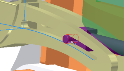
- The next joint to add is the one between the blade set and the follower, so that the follower travels in the blade clamp.
Before you create that joint, lock the Prismatic Joint between the Guide and Follower components. This action prevents the related components from moving, and lets the solver work more efficiently.
Right-click the Prismatic:3 (Guide:1, Follower:1) joint and click Lock dofs.
- In the ribbon bar, click the Dynamic Simulation tab to display the simulation commands. Now add the sliding joint.
- In the Joint panel, click Insert Joint. In the pull down list, select Sliding: Cylinder Curve. For input 1, select the blade clamp slot profile on which the follower rides.
- For input 2, select the Follower cylinder face that rides in the slot. Click OK.

- Unlock the prismatic joint.
That completes this chapter on adding components and joints to the assembly. In this chapter, you learned to:
- Add assembly components while in the simulation environment.
- Add assembly constraints and see them automatically create standard joints.
- Add joints to simulate mechanical conditions within the assembly.
| For more information | Location |
|---|---|
| Tutorial | Simulation - Fundamentals - Part 2 |