With the necessary parameters in place, we can now add logic to the model using rules. Rules can be defined for various actions, including setting the values of parameters and activating or suppressing features. Our first rule suppresses a feature on a part.
Rule Editor
-
 On the ribbon, click
Manage tab
 iLogic panel
 Add Rule
.
 - Enter Modify_Feature in the Name field of the Rule Name dialog box, and click OK to display the Edit Rule dialog box.
The Edit Rule dialog box is the heart of the iLogic functionality. You use this dialog box to create and edit iLogic rules.
- Select the Model tab. The top left panel of this window includes a view of the Model tree. Click the Model Parameters node in the tree. Notice that the top right panel now lists only the Model parameters.
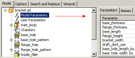
To see other sets of parameters, you can click the User Parameters node in the model tree to display only the manually created parameters.
You write rules in the rule text area, which is located in the bottom panel of the Edit Rule dialog box. You can enter Rule keywords by typing them directly into the text entry field. Or, you can select generic statements from the toolbar above the field and then edit the statements.

This tutorial describes entering the statements manually, unless otherwise indicated.
- Click the User Parameters node to display the User parameters.
The bracket model includes two holes: one in the base, and one on the flange.
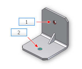
(1) flange hole (2) base hole
Our new rule turns on (or off) the base hole, the flange hole, or both. In a previous lesson, we created a multi-value parameter named holes. We assigned three values to this parameter labeled base, flange and none. The rule turns on the flange hole when flange value is selected. Choosing base turns on the base hole, and a value of none turns off both holes
Add Parameters to Rule
Now we can create the rule. We begin with the flange setting of the holes parameter.
- Enter If in the text box, followed by a space.
Notice that the text of the If keyword turns bold and red. The red color indicates a recognized language element (in this case a keyword).
- In the Model tree, click the User Parameters node, then double-click holes to insert the holes parameter name into the editor.
- Type = , followed by a space, and then type “flange” (be sure to include quotation marks). Add another space, and type Then to finish this line.
Notice that the different colors are applied automatically to the different language elements of the expression defined so far. This color coding makes rules much easier to read, and it helps you quickly comprehend their meaning, and identify any information entered incorrectly.

- Press Enter to move to the next line.
We can make the flange hole active by using an iLogic function.
Insert Code Snippets
- In the Snippets area on the left side of the editor, click the System tab. Expand the Features node, then double-click the IsActive choice to insert its text into the rule editor.
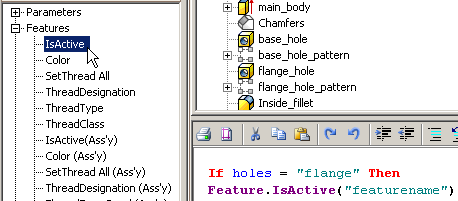
- Click the Model tab at the top of the Edit Rule dialog box, and click flange_hole in the Model tree.
- Click the Names tab in the top right corner of the dialog box, and notice that flange_hole now appears here.
- Highlight featurename in the rule text, and then double-click flange_hole in the Names tab to replace featurename with flange_hole.
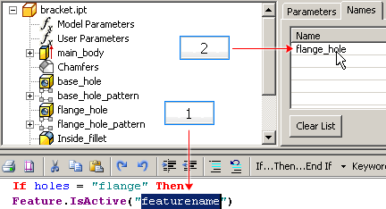
(1) Highlight generic text. (2) Double-click name to replace highlighted text.
The Feature.IsActive function sets the activity state (suppression state) of a feature specified in quotation marks inside the parentheses.
- To assign a value of True, first insert a space at the end of the statement. After the space, enter =, followed by another space, and then the word True.
Assigning a value of True indicates that the flange hole is active (unsuppressed). When the flange option is chosen for the holes parameter, we want only the flange hole active. We must include a command that deactivates the base hole.
- At the end of your rule text, press Enter to move to the next line, and then insert another Feature.IsActive(“featurename”) function.
- Highlight the featurename string and click base_hole in the Model tree. Then double-click base_hole in the Name tab to replace featurename with base_hole, and assign a value of False.
These two lines turn on the flange hole and turn off the base hole. Your rule now consists of three lines.

Copy Code Block
If holes = "flange" Then
Feature.IsActive("flange_hole") = True
Feature.IsActive("base_hole") = False
For instances in which the base hole must be activated, a similar strategy is employed. We must activate the base hole and deactivate the flange hole.
Reuse Code Blocks
To create the next part of the rule, you copy and paste the reusable portion of the previous statements. Then change the pasted text as required.
- Press Enter to insert a new line, and then enter ElseIf.
- Highlight the reusable text, which includes everything after the word If, and press Ctrl + C to copy the text to the clipboard. Then, position the cursor after ElseIf, and press Ctrl + V to paste it. Note: You can also Cut, Copy, and Paste by right-clicking selected text and selecting the appropriate command from a context menu. It also contains other editing commands. Or, you can use the icons in the editing toolbar above the rule text area.
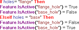
- In the newly pasted text, change flange to base, and switch the True and False conditions.
Copy Code Block
If holes= ”flange” Then
Feature.IsActive(“flange_hole”) = True
Feature.IsActive(“base_hole") = False
ElseIf holes = “base” Then
Feature.IsActive(“flange_hole”) = False
Feature.IsActive(“base_hole”) = True
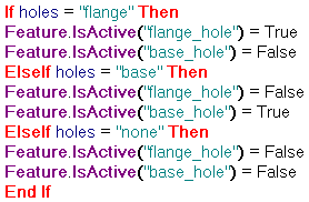
- Add another ElseIf statement, and use the same copy and paste method to create the third part of this rule, where no holes are required. Modify the newly pasted text to suppress both hole features when the holes parameter is set to none.
- Finish the statement by typing End If (or clicking the corresponding keyword button).
The rule is complete.
Copy Code Block
If holes = "flange" Then Feature.IsActive("flange_hole") = True Feature.IsActive("base_hole") = False ElseIf holes = "base" Then Feature.IsActive("flange_hole") = False Feature.IsActive("base_hole") = True ElseIf holes = "none" Then Feature.IsActive("flange_hole") = False Feature.IsActive("base_hole") = False End If - Click OK on the Edit Rule dialog box.
If there are no mistakes, the dialog box closes without an error message. An icon representing the new rule appears in the Rule Browser.
-
 To verify the new rule, click
Manage tab
 iLogic panel
 Rule Browser
and view the tree.
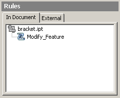
The Rule Browser provides a way for you to see the rules in the current model. We explore the Rule Browser further later in this tutorial.
Test the Feature Suppression Rule
- On the ribbon, click
Manage tab
 Parameters panel
 Parameters
to display the Parameters dialog box.
 - Click the node icon to the left of the Model Parameters area to collapse the list of Model parameters.
- Click in the Equation field of the holes parameter to enable the multi-value drop-down arrow. Then click the arrow and select flange from the drop-down menu.
- Click any other cell and observe the bracket. The only hole shown is the flange hole.
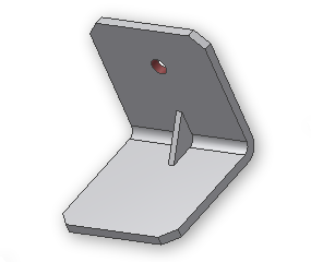
- Change the multi-value selection to base, and click another cell. Only the base hole is shown.
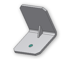
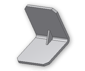
- Finally, change the multi-value selection to none, and click another cell. No holes are visible.
- Click Done to close the Parameters dialog box.
Rename the Feature Suppression Rule
The rule we created requires a more descriptive name.
-
 On the ribbon, click
Manage tab
 iLogic panel
 Rule Browser
.
 - In the tree, click Modify_Feature once to highlight the rule, then click it again to enable edit mode.
- Rename the rule to Hole_Rule, and press Enter.
- Close the Rule Browser.