-
 Click Sketch tab
 Draw panel
 Line on the ribbon, or press L to invoke the Line command. You can also right-click in the graphics window and select Line at the top of the marking menu.
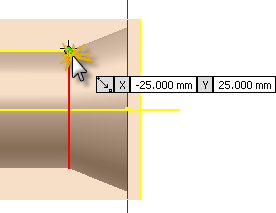
 - Left-click the point shown to begin the first point of the line. A green dot appears to indicate that you have selected the precise endpoint of the projected line. The Heads-Up Display (HUD) Pointer Input displays the line starting coordinates as X = -25 mm, Y = 25 mm.

- Move your cursor to the left (180°). End the first line segment by clicking where the horizontal line intersects with the start of the spherical radius. Do not be concerned with the displayed value in the value input box.

- The first sketch line is now complete. The Line command can also be used to draw an arc radius. For the starting point of the arc, click the endpoint of the line you just drew. Press and hold the left mouse button and drag your cursor to trace over a portion of the spherical radius.

- The length of the arc segment is not important. Drag your cursor just enough to approximate what you see in the image. Be sure to keep your cursor on the spherical radius to ensure that the arc ending point is coincident with the projected geometry. (A yellow dot at the end of the cursor and a coincident constraint symbol appear when you are coincident with the sketch geometry.) Click to set the ending point of the arc.
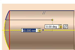
- You now use the Dynamic Input Heads-Up Display (HUD) to sketch another line with a precise distance and angle. Still in the Line command, pick the ending point of the arc you just completed and move your cursor to the right. Two value input boxes appear near your cursor indicating the length (distance) and angle of the sketch line under construction. Notice that the first value input box is highlighted and awaits your input. Enter 60 in the box for the line length and press the Tab key to shift the input focus to the second value input box. Enter 0 for the line angle and press the Tab key again.
- Observe the small lock icon within each value input box. They indicate that the values you entered are locked (constrained) for both the distance and angle of the line. Note also the two parallelism glyphs indicating that the two sketch lines are exactly parallel.

- Press Enter to finish drawing the line. The dimensional values, called persistent dimensions, are created and placed when Dynamic Input is used to define sketch geometry.
- Next, draw the final line segment back to the point at which you started. When the green dot appears, click to complete the segment and close the profile.
- Finally, right-click and select Done [Esc] from the marking menu, or press the Esc key, to exit the Line command.
We will now create a vertical dimension to specify the width of the profile.
-
 Click Sketch tab
 Constrain panel
 Dimension on the ribbon, or press D to invoke the Dimension command. You can also right-click in the graphics window and select General Dimension from the marking menu.
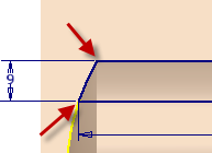
 - Select the two line endpoints shown in the image. (The endpoints appear as red dots when you place your cursor over them.) Move your cursor to the left and click to place the dimension.
- Enter 9 in the Edit Dimension text box. Click the green arrow (or press Enter) to create the dimension.

- Right-click and select Done [Esc] from the marking menu to exit the Dimension command.