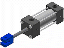
An iAssembly factory can contain both parts and subassemblies as components.
In this example, you can create the housing and shaft subassemblies. In each subassembly, replace regular components with members (iParts or iAssemblies), where appropriate.
- Create assembly files for subassemblies and add iPart or iAssembly members as components. In this example:
- Create a subassembly of the housing that contains the cylinder body and bolt iParts.
- Create another subassembly of the shaft and include the shaft iPart.
- Create an assembly file for the top-level assembly. Place a shaft member and a housing member as components.
- On the ribbon, click
Manage tab
 Author panel
 Create iAssembly
to convert the assembly to a factory. In the iAssembly Author, use Table Replace for the shaft and housing.
 - On the Components tab, expand the housing subassembly, select Table Replace, and click the Add arrow to make it a configurable item. Repeat for the shaft subassembly. Tip: Because these subassemblies contain components that are also iParts or iAssemblies, a Table Replace column is created. When editing the table, you can replace the member in the row with another member of the same factory.
- On other tabs, add additional configurable items such as relationships whose values must be different for individual members or material. Each added item creates a column in the table.
- In each member row, modify cell values that differentiate members.
- On the Components tab, expand the housing subassembly, select Table Replace, and click the Add arrow to make it a configurable item. Repeat for the shaft subassembly.
- Click Verify to check syntax and verify that all cells contain valid units. If errors are found, make corrections.
- If appropriate, click Options to modify the naming scheme. By default member names are the file name, incremented for each row, as in shaft-01, shaft-02, and so on.
- When you finish, click OK to close the iAssembly Author. Save the file.
Note: You can edit columns and rows in an Excel spreadsheet and take advantage of calculations to create data. You can change the order of columns, but cannot change the column headings.