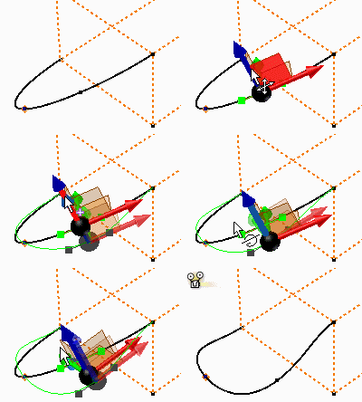
Use options on the context menu to adjust the shape of a 2D or 3D interpolation spline using the handles. A handle is tangent to an endpoint or fit point.
Adjust the handle length by dragging grips to modify the distance the spline is tangent to the handle. The handle can be dimensioned and constrained to control its length and orientation, which controls the spline weight at a given fit point.
Use Display Curvature to see the effect of adjustments made to the tangent handle.
Drag or add dimensions to adjust tangent handles
- Right-click a 2D or 3D spline, and then select Activate Handle. A handle displays on the spline nearest the selection point.
- Click a grip at the end of the handle, and then drag in the direction of the tangency.
If appropriate, click a face on the view cube or click Look At on the navigation bar and click a planar face. The view aligns with the point of contact at the endpoint and the x axis is aligned with the tangential direction.
- If desired, click
3D Sketch tab
 Constrain panel
 Dimension
and select a handle. Enter a unitless dimension to adjust the tangent handle length (where 1 represents neutral).
 Experiment to see the effect of the dimension. For example, enter 2 to increase the length and cause the handle to "hug" the curve twice as much. Enter 0.5 to decrease the handle length and decrease the distance the handle is tangent to the spline.
- When the tangency is adjusted as needed, right-click, and then select Done.
Use 3D Move/Rotate to adjust tangent handles

The 3D coordinate triad shows X, Y, and Z planes. The red arrow indicates X, the green arrow is Y, and the blue arrow is Z. Click any part of the triad to set movement.
The triad is first positioned at 0,0,0 but thereafter remembers its location.
- Right-click a 3D spline handle and select 3D Move/Rotate. The 3D triad is positioned on the fit point.
- Rotate the view to see the triad axes.
- Select a triad segment to enter values relative to the selected geometry.
- Click an arrowhead to move along the selected axis.
- Click an arrow shaft to enter a rotation angle around the selected axis.
- Click a plane to enter distances on that plane. The third plane is not available.
- Click the triad sphere to enter distances in all three axes.
- If desired, click
 to specify new origin coordinates. Entered values are relative to the new origin.
 - If desired, click the Move triad only check box to enter coordinates for the triad only, not sketch geometry.
- Click OK to quit.