Next we define the boundary conditions by adding structural constraints and loads. We start with constraints first.
- In the Constraints panel, click Fixed
 . The dialog box displays with the Location selector active.
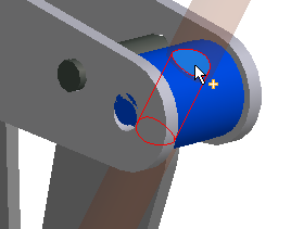
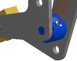
 - Select the two holes through which the screw passed. They are the holes that are left after excluding the screw from the simulation.


- Click OK. The two faces are axially constrained, as if the screw were there.
Now, we assign loads on the components.
- In the Loads panel, click Force
 . The dialog box displays with the Location selector active.
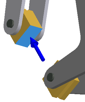
 - Select the face on the ch_09-Upper_Grip component as shown.

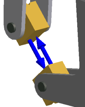
- In the dialog box, enter 100 for the Magnitude value, and click OK.
- Repeat the previous steps for the ch_09-Lower_Grip component.

- Click OK to exit the Force dialog box.