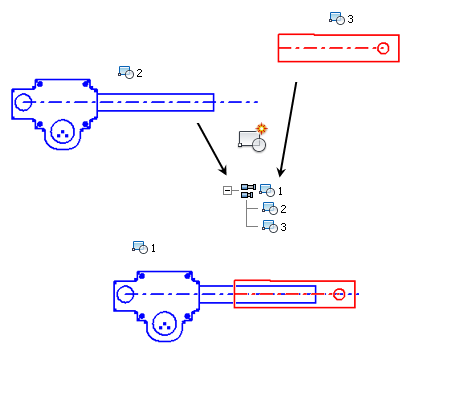
When you include block instances in a new sketch block, you create a nested block. You use nested blocks and the Flexible attribute to simulate kinematic subassemblies. For example:

- In a 2D sketch, create geometry and place constraints to simulate a hydraulic cylinder.
- Create one sketch block, PISTON, that includes the piston geometry and a centerline along the piston axis.
- Create another sketch block, CYLINDER, that includes the cylinder geometry and a centerline along the cylinder axis.
- Create a collinear constraint between the piston and cylinder centerlines.
- Create a third sketch block, HYD CYLINDER, that includes the PISTON and CYLINDER blocks. HYD CYLINDER is a nested block.
- Click on a portion of the geometry and drag.
Note that all the geometry moves with the cursor. You need to make the nested block flexible so the PISTON and CYLINDER sketch blocks can move relative to one another.
- Right-click the HYD CYLINDER instance in the browser and set the Flexible attribute. The degrees of freedom between PISTON and CYLINDER are now available.
- Click on a portion of the PISTON geometry and drag to simulate the kinematics of the hydraulic cylinder.
Simulate hydraulic cylinder:
To add or change constraints between the blocks, edit the nested block definition.