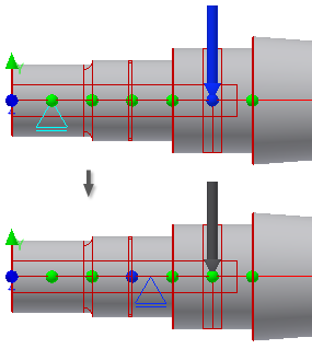
When you switch to the Calculation tab, notice how the 2D and 3D Previews change. Not only the graphical representations of loads and supports are displayed, but there are also green and blue position markers.
For each section, the program shows three position markers: one at each end of a section, and one position marker in the middle of each section. A blue position marker means that load or support is positioned on such a position marker.
Note: Supports are represented by triangles. Loads are represented by arrows.
- Select Supports from the drop-down menu in the Loads & Supports region.
- Press and hold the Alt key. In the Autodesk Inventor window, drag the support to the second shaft section from the left as shown on the image.

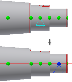
The nearest blue position marker indicates that the support is positioned towards it.
Note: The position marker can be half-blue and half-green if it is between two sections. - Double-click the support to display the Free Support dialog box, and change the Distance from middle of section field to 1.5 mm, which is the distance from the currently active position marker to the support.
- Click OK.
- In the Autodesk Inventor window, press and hold the Alt key, and then drag the second support indicator to the shaft section located on the right end of the shaft, as shown.
