Next, you use the imported sketch to remove material from the part.
- Use the View Cube to change your view so that the sketch is visible.
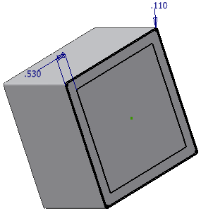
- Click the Extrude command
 , and then click inside the inner loop of the sketch. The preview indicates the current extrude distance.
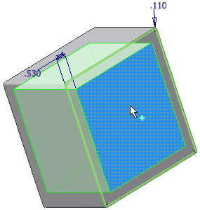
- In the Extents field of the Extrude dialog box, select To Next from the drop-down menu. If you are using the mini-toolbar, select To next face/body from the drop-down menu.
- In the Extrude dialog box, or from the mini-toolbar, click Cut.

Within the selected region of the box part, you should see a direction indicator pointing to the inside of the box. The indicator shows the direction of the cut extrusion. Though dim, the direction indicator is visible in the highlighted portion of the image.
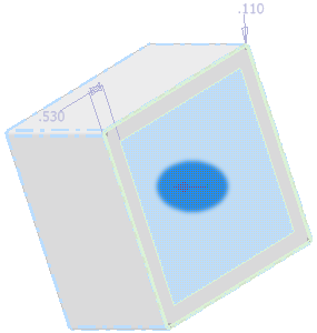
- To see the indicator more clearly, click the Flip Direction button in the dialog box, or from the mini-toolbar.
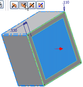
- Click the other Flip Direction button. Ensure the indicator points to the inside of the box.
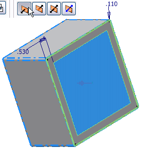
- Click OK to create the cut. Because you selected To Next from the Extents menu, or To next face/body from the mini-toolbar, the cut terminates on the next face it encounters. In this case, it is the back face of the box.
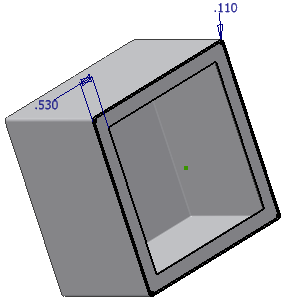
- In the browser, right-click Sketch1 (nested under Extrusion1), and then remove the check mark next to Visibility.
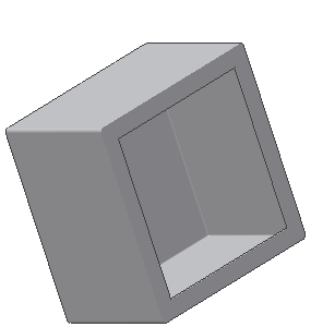
- Save the part.