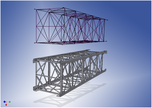
In the skeletal modeling method, you put all known factors into a skeleton file. Then you use it as a base for most of the subassemblies and parts that make up the assembly.
A skeleton file can contain any type of element in any combination. The following is typical information created in a skeleton file:
- Sketches Define the concept of the final product, or use as a layout of different areas of the assembly.
- Work geometry Defines important connection points, axial directions, and work planes that define assembly levels.
- Parameters Define important values for part size, angles for placements, and other known values for the design.
- Solids Define volumes for final assembly as a single part or for defining subareas of the design.
Advantages
- Simple assembly or component creation.
- Easy design modification.
- Reference common connections or critical locations from a single file.
Disadvantages
- Slight data volume increase.
- Additional creation of skeleton sketches.
Inventor commands
- Sketch blocks
- Sketch constraints
- Make Part
- Make Components
- Derive
- Adaptivity