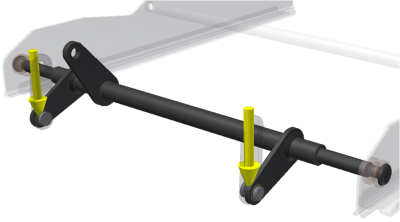
To simulate conditions your design can encounter, you add force loads to areas where such forces can be encountered. There are various load types to use. The following list explains the available load types.
|
Load |
Load-Specific Information |
|
|---|---|---|
|
|
Force |
Apply a force to a set of faces, edges, or vertices. When the force location is a face, the direction is automatically set to the normal of the face. The force points to the inside of the part. Define the direction planar faces, straight edges, and axes. |
|
|
Pressure |
Pressure is uniform and acts normal to the surface at all locations on the surface. Apply pressure only to faces. |
|
|
Bearing Load |
Apply a bearing load only to cylindrical faces. By default, the applied load is along the axis of the cylinder and the direction of the load is radial. |
|
|
Moment |
Apply a moment only to faces. Define direction using planar faces, straight edges, two vertices, and axes. |
|
|
Body Loads |
Specifies the linear acceleration for the model using a face as input. Cylindrical selections provide an axial direction. You can only apply one body load per analysis. |
|
|
Gravity |
Specifies the direction of gravitational load on the model. Select a face to define the direction or use Vector Components to control the direction precisely. Cylindrical selections provide an axial direction. |
Add a load
- Click the load command corresponding to the load type you want to add.
- The selection command is active so you can select the geometry appropriate to the load you are defining.
- Specify the load parameters. When needed, expand the dialog box to access the advanced settings.
Double-click the load node in the browser to modify it. Alternatively, you can right-click the load node and click Edit [type] constraint.