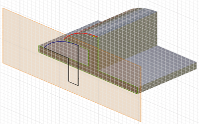
Reference geometry consists of sketch curves or points. It is created by projecting the model edges, vertices, or work features of another sketch onto the active sketch plane. Reference geometry refers to (is associated with) previously created geometry.
Reference geometry is created in two ways:
- All edges of the face are automatically added to the active sketch as reference geometry when you create a sketch on the planar face of a model.
- The Project geometry command projects model edges, vertices, work features, points, or curves from a visible sketch onto the active sketch planes as reference geometry.
Work Point
Work features are abstract construction geometry used when geometry is insufficient for creating and positioning new features. To fix position and shape, constrain features to work features.
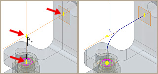
You can place or project work points onto part faces, linear edges, or onto an arc or circle. Work points can be constrained to the center points of arcs, circles, and ellipses.

Work Axes
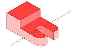
When creating features and assemblies, use work axes to mark symmetry lines, centerlines, or distances between revolved feature axes.

Work Planes
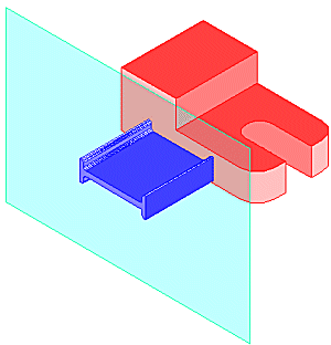
Use work planes to create axes, sketch planes, termination planes, or to position cross-sectional views or cutting planes.
Guidelines for using a work plane:
- A part face is not available as a sketch plane for sketching new features.
- An intermediate position is required to define other work planes (for example, at an angle to a face at an offset distance).
- Work planes should be placed at the center of cylindrical shapes and used to anchor parametric dimensions between cylindrical features.
