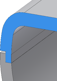
We will now build a lip-groove combination to facilitate placing the mating parts in a physical assembly. Orient the view to the inside of the part like the following image.
- On the ribbon, click
3D Model tab
 Plastic Part panel
 Lip
.
Lip
. - Make sure the Lip button is selected in the dialog box.
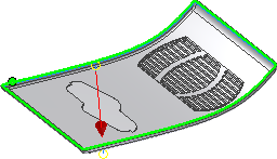
- On the Shape tab:
- Select the inside edge as the Path Edges.
- Leave the Path Extents unchecked.
- Click the Pull Direction check box.
- Select the Y Axis in the Origin folder as the pulling direction.
- On the Lip tab:
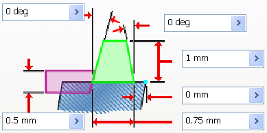
- For Outside Angle, enter 0 deg.
- For Inside Angle, enter 0 deg.
- For Height, enter 1 mm.
- For Shoulder Width, enter 0 mm.
- For Width, enter 0.75 mm.
- For Clearance, enter 0.5 mm.
- Click OK to create the lip.
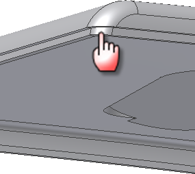
- In the Solid Bodies folder in the browser, use the context menu to turn off the Visibility of the top body. Turn on the visibility for the bottom body. Orient the view to the inside of the part like the following image.
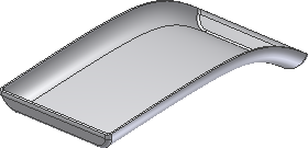
Next, we will use the Lip command to create the mating groove.
- Click the Lip command.
- On the Shape tab:
- Make sure the Groove button is selected.
- Select the inside edge as the Path Edges.
- Leave the Path Extents unchecked.
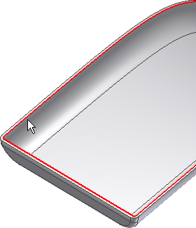
- Click the Pull Direction check box.
- Select the Y Axis in the Origin folder.
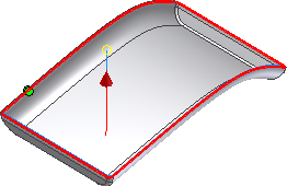
- On the Groove tab:
- For Outside Angle, enter 0 deg.
- For Inside Angle, enter 0 deg.
- For Height, enter 1 mm.
- For Shoulder Width, enter 0 mm.
- For Width, enter 0.75 mm.
- For Clearance, enter 0 mm.
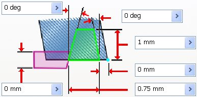
- Click OK to create the groove.
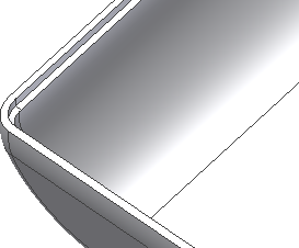
The mating lip and groove features are shown in the following cutaway view.
