 |
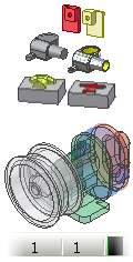
You can create a derived part using another part. The source is called the base component in the new file. You can include or exclude work features, sketches, constraints, iMates, and parameters in a derived part. |
A derived part may be scaled or mirrored from the original part.
Derive a part
Select features, surfaces, visible 2D and 3D sketches, work features, parameters, and iMates to include or exclude from the derived part. Sketches that are not shared or consumed by features are included in the base part. You can also specify whether the derived part becomes a solid or a surface in your new file.
To begin, create a part file. If you want to create a multi-body part file, create one or more features or bodies. If you want to create a part with no pre-existing features or bodies, choose Finish Sketch when you start the new part to close the default sketch.
- On the ribbon, click
Manage tab
 Insert panel
Derive
.
Insert panel
Derive
. - In the Open dialog box, browse to the part file (.ipt) to use as the base part, and then click Open.
- Select the Derive style.
 Creates a single solid body derived part with no seams between planar faces.
  Creates a single solid body derived part with seams between planar faces.
  Creates a derived part with one or more solid bodies if the source part contains multiple bodies. This is the default option.
  Creates a derived part with a single surface body.
 - In the Derived Part dialog box, model elements are displayed in a hierarchy. Accept the default or use the Status buttons at the top to change the status of all selected objects quickly. You also can click a status icon next to an individual object and toggle the status options.
If the source part contains only one body, it is displayed in the graphics screen. If the source part is a multi-body part with only one visible body, it is displayed in the graphics screen. If the source part is a multi-body part with more than one body visible, no bodies are displayed in the graphics screen. To specify the body or bodies to include, expand the Solid Bodies folder and use the Status button to include or exclude bodies. If you want to include all bodies, you can select the Solid Bodies folder and then click the include status button.
Note: Only bodies that are visible in the source part file are selectable. Selects element for inclusion in the derived part.
  Excludes element in the derived part. Items marked with this symbol are ignored in updates to the derived part. Note: If you select a nonexported object for inclusion in the derived part, a confirmation message appears when you close the Derived Component dialog box notifying you that the base file marks the object for export.
 - If required, click Select from Base
 to allow graphical selection of components from the base component window. After you select the components, click Accept Selection
  .
. - If required, turn off the Show All Objects check box to display only exported elements in the list.
- Specify scale factor and mirror plane:
- Accept the default scale factor of 1.0 or enter any positive number.
- If required, select the check box to mirror the derived part feature from the base part. Click the down arrow to select an origin work plane as the mirror plane.
- Click OK. Note: If you select a geometric group, such as surfaces, for inclusion in the derived part, any visible surface later added to the base part is derived when you update.