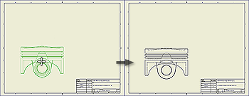
The first view in a new drawing is a base view. On the ribbon, click
Place Views tab
 Create panel
Base
to add additional base views to a drawing.
Create panel
Base
to add additional base views to a drawing.
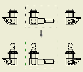
A base view is the source for subsequent views. A base view:
- Sets the defaults for child views.
- Can be used to create a projected view, an auxiliary view, a section view, and a detail view.
|
|
|
 |
Note: Parts with the BOM Structure set as Reference are not included in the formula for creating the default size of the view bounding box. As a result, the Reference parts can be clipped in drawing views. To extend the size of the view bounding box, increase the Margin value on the Model State tab of the Drawing View dialog box.
|
Tip: Default settings and values in the Drawing View dialog box are defined in the current standard and can be changed by using the Style and Standard Editor.
 Show Me how to create a base view