On the ribbon, access the Ground Plane Settings dialog box.
- On the View tab
 Appearance panel Ground Plane drop down list, click Settings.
Reorient the ground plane
- Modify the ViewCube orientation. Orient the camera to look down toward a location for the ground plane. Then, in the ViewCube context menu, select “Set current view as Top”.
Position the ground plane
- On the View tab Appearance panel Ground Plane drop down list, click Settings...
 . The ground plane, if not visible, displays. You can see adjustments you make relative to the model display.
 - The ground plane origin triad displays at the model origin. To enable positioning changes, select Manual Adjustment. In the graphics window, click and drag a triad arrow to use directionally constrained positioning, and the center sphere to use three-dimensional positioning for the origin.
While changing position, the object snapping effect is activated, simplifying model vertex selection.
Note: The triad does not accept rotational input.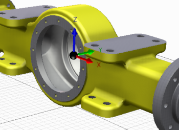
The cursor snaps to model vertices, but selections are non-associative.
Resize the ground plane manually
- On the ribbon View tab Appearance panel, Ground Plane drop down list, click Settings.
- In the dialog box, Select Manual Adjustment.
- In the graphics window, select a ground plane boundary line or corner, and drag to resize it.
Note: To set the ground plane to resize automatically, select Automatically adjust to model. This option also automatically adjusts the location to the lowest point of the model geometry.