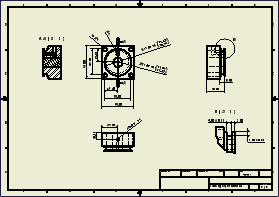
A drawing communicates engineering design to manufacturing, purchasing, customer service, and others. Each company has standards for drawing content, based on the type of product and on established internal processes.
When you create a drawing file, it opens with a default sheet containing the border, title block, and other elements specified in the template.
Drawing format
When you create a drawing, you can use the default template, another predefined template, or a custom template that incorporates conventions and standard elements used by your company.
Standard drawing templates are installed with Autodesk Inventor LT. During installation, you specify which standard to use as the default. Your selection adds the appropriate default drawing template to the Templates directory.
The default template is Standard.idw. You can customize this file or create other templates.
Drawing views
Start by specifying a base view, and then select a part file for the view. You can create views of multiple parts in the same drawing.
If your sheet format includes predefined drawing views, views are added automatically.
Drawing annotations
After placing views, add notes, dimensions, centerlines, center marks, symbols, and other annotations. The default attributes for most annotations are controlled by styles in the style library associated with the active drafting standard. If you are not using a style library, define annotation styles and store them in the drawing template file.
You can use the model dimensions defined in the design phase or add drawing dimensions that serve as annotations but do not alter the model. You can change model dimensions from the drawing, if that option was selected when Autodesk Inventor LT was installed.
A drawing sketch is a special form of annotation. If a view is selected when you create a sketch, the sketch is associated with the view. Use the commands on the sketch tab to draw 2D sketch geometry. After you close a sketch, you can add drawing dimensions and associate symbols to the sketch geometry.
Printing a drawing
You can print all or just part of your drawing. Set the print options to print the appropriate portion of the drawing.
Use the Multi-Sheet Plot wizard to print multiple drawing sheets that include drawings of various sizes. You can select IDW, 2D DWF, and DWG files.
Model iProperties in drawings
Drawing Document settings provide a mechanism to copy values of selected model iProperties to the drawing iProperties on the first view creation. Copied model iProperties can be used in title blocks and other annotations that access model or drawing iProperties.
Model iProperties copied to a drawing are not refreshed automatically when the model is updated. Use the Update Copied Model iProperties command to refresh the iProperties.
Model iProperties are copied and updated in the drawing from a source model. The source model is always the top model from the first drawing view on the first drawing sheet. The source model is not available if:
- The first drawing sheet does not include a drawing view.
- The first drawing view on the first drawing sheet does not reference a source model.
- The referenced model file is not resolved.
Custom iProperties in drawings
Use the Additional Custom Model iProperty Source option in drawing Document Settings to make custom iProperties from an external file available in the drawing.
Additional custom iProperties are added to the Custom Property - Model list in the Format Text dialog box. The original drawing custom properties do not change.
Tip Add custom iProperties from an external file:
- To create sketch objects (a title block, border, or sketched symbol) in a drawing or template before you place model views.
- If the source model does not include the desired custom iProperties.