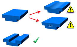
Sink marks and voids both result from localized shrinkage of the material at thick sections without sufficient compensation.
Sink Marks
Sink marks appear as depressions on the surface of a molded part. These depressions are typically very small; however they are often quite visible, because they reflect light in different directions to the part. The visibility of sink marks is a function of the color of the part as well as its surface texture so depth is only one criterion. Although sink marks do not affect part strength or function, they are perceived to be severe quality defects.
Voids
Voids are holes enclosed inside a part. These can be a single hole or a group of smaller holes. Voids may have severe impact on the structural performance of the part.
Causes
Sink marks are caused mainly by thermal contraction (shrinkage) during cooling. After the material on the outside has cooled and solidified, the core material starts to cool. Its shrinkage pulls the surface of the main wall inward, causing a sink mark. If the skin is rigid enough, deformation of the skin may be replaced by formation of a void in the core.
-
Localized geometric features. sink marks typically occur in moldings with thicker sections, or at locations opposite from ribs, bosses or internal fillets.
-
High volumetric shrinkage.
-
Insufficient material compensation. Early gate freeze off or low packing pressure may not pack the cavity properly.
-
Short packing or cooling time.
-
High melt and/or mold temperatures.
Voids are caused when the outer skin of the part is stiff enough to resist the shrinkage forces thus preventing a surface depression. Instead, the material core will shrink, creating voids inside the part.

Remedies
-
Optimize packing profile. As sink marks occur during packing, the most effective way to reduce or eliminate them is to control the packing pressure correctly. To determine the effects of packing on sink marks, use a simulation package such as Autodesk Simulation Moldflow Insight.
-
Change the part geometry. Change the part design to minimize thick sections and reduce the thickness of any features that intersect with the main surface.
-
Reduce volumetric shrinkage.
-
Relocate gates to problem areas. This allows these sections to be packed before the thinner sections between the gate and the problem areas freeze.
-
Optimize the runner system design. Restrictive runner system design can result in premature gate freeze off.
-
Use a different material.
Solving one problem can often introduce other problems to the injection molding process. Each option hence requires consideration of all relevant aspects of the mold design specification.