Gates can have many different configurations but they are broadly classified based on the method of gate removal into manually trimmed and automatically trimmed gates. Manually trimmed gates require an operator to separate the parts from runners during a secondary operation.
- The gate is too large to be sheared from the part as the tool is opened.
- Some shear-sensitive materials, such as PVC, should not be exposed to the high shear rates inherent to the design of automatically trimmed gates.
- Simultaneous flow distribution across a wide front to achieve specific orientation of fibers or molecules often precludes automatic gate trimming.
- Direct or sprue gate
- Disc or diaphragm gate
- Edge or standard gate
- Fan gate
- Film or flash gate
- Overlap gate
- Ring gate
- Spoke or spider gate
- Tab gate
- Direct or sprue gate
-
A direct gate is commonly used for single-cavity molds, where the sprue feeds material directly and rapidly into the cavity with minimum pressure drop, as shown in the following diagram.


The disadvantage of using this type of gate is the gate mark left on the part surface after the sprue is trimmed off. Freeze-off is controlled by the part thickness rather than determined by the gate thickness. Typically, the part shrinkage near the sprue gate will be low; shrinkage in the sprue gate will be high. This results in high tensile stresses near the gate.
Dimensions:
The starting sprue diameter is controlled by the machine nozzle. The sprue orifice diameter here must be about 1mm larger than the nozzle exit diameter. Standard sprues can have tapers from 0.5 degrees to 1.5 degrees (1.0 degrees to 3 degrees included angle) with a common size of about 1.2 degrees taper angle (1/2 inch per foot included angle). Therefore, the sprue's orifice diameter and length will control the diameter of the sprue where it meets the part. Typically, the sprue diameter will be well over double the wall thickness of the part, controlling the molding cycle time.
A smaller taper angle (a minimum of one degree) risks not releasing the sprue from the sprue bushing on ejection. A large taper wastes material and extends the cooling time.
Non-standard sprue tapers will be more expensive to machine, with little gain.
- Disc or diaphragm gate
-
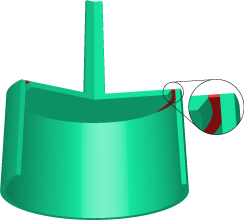
A disc gate is often used for gating cylindrical or round parts that have an open inside diameter. This gate is useful when concentricity is an important dimensional requirement, and the presence of a weld line is objectionable. These gates are typically difficult and expensive to trim from the part.
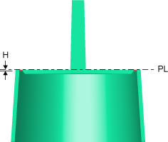
As shown in the following diagram, the disc gate has a thin land around the inside edge of the part, which facilitates the removal of the gate. Since the disc is fed from a concentric sprue or hot drop, uniform flow to all parts of the gate is easy to maintain.
Dimensions:
The typical gate thickness (H) is 0.2 to 1.3 mm.
- Edge or standard gate
-
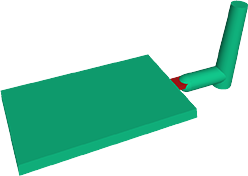
An edge gate is located on the parting line of the mold, as shown in the following diagram. The gate cross section is rectangular and can be tapered in width and/or thickness between the part and runner.


Dimensions:
The typical gate thickness (H) is 25 to 75 percent of the part thickness, and the width is typically two to ten times the thickness. The gate land should be short, typically 0.5 to 1.0 mm in length. Larger parts can have longer land lengths.
- Fan gate
-
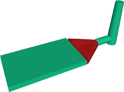
A fan gate is a wide edge gate with variable thickness, which permits rapid filling of large parts or fragile mold sections through a large entry area. Fan gates are used to create a uniform flow front into wide parts where warpage and dimensional stability are main concerns.
As shown in the following diagrams, the fan gate tapers in both width and thickness, to ensure the following:
- The flow front velocity will be constant across the entire width
- The entire width is being used for the flow
- The pressure is the same across the entire width


Dimensions:
Well-designed fan gates have a narrow land, typically 2.0 mm or less. This land will be very thin, typically under 1 mm. The gate width is typically 25 mm to as wide as the part.
The main body of the gate will be thin in the center and thick on the edges to promote flow to the outer edges.
- Film or flash gate
-
A film gate consists of a straight runner and a gate land across the entire width of the cavity or a portion of the cavity, as shown in the following diagrams.
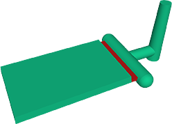


It has the same objectives as a fan gate but it is more difficult to achieve. The thin land of the gate has areas that cause hesitation, and it is very sensitive to the thickness of the land, diameter of the runner and flow rate.
Dimensions:
The typical gate size is small, approximately 0.2 to 1.0 mm thick (H). The land area (gate length (L)) must also be kept small, typically under 1 mm.
- Overlap gate
-
An overlap gate is similar to an edge gate but a portion of the gate overlaps the part as shown in the following diagrams.
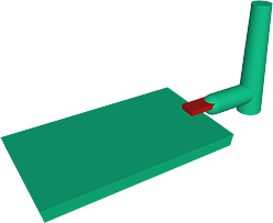


Dimensions:
The typical gate thickness(H) is 25 to 75 percent of the part thickness, and the width is typically 2 to 10 times the thickness. The gate land should be short, typically 0.5 to 1.0 mm in length. Larger parts can have longer land lengths.
- Ring gate
-
With a ring gate, the material flows freely around the core before it moves down as a uniform tube-like extrusion to fill the mold, as shown in the following diagrams.

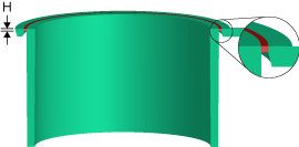 Note: In practice this is difficult to achieve because the gate relies on hesitation in the thin gate land to achieve a balanced fill. Uniform fill is sensitive to the gate land, runner around the part and the injection time.
Dimensions:
The typical gate thickness (H) is 0.2 to 1.5 mm.
- Spoke or spider gate
-
The spoke gate, which is also called a four-point gate or cross gate, is shown in the following diagrams. This gate is used for tube-shaped parts and offers easy gate removal and material savings. Disadvantages are the possibility of weld lines and the fact that perfect roundness is unlikely.


Dimensions
The gate cross section can be rectangular like an edge gate and will have similar nominal dimensions, or it can have a circular cross section and be configured like a circular tapered gate.
- Tab gate
-
A tab gate is typically employed for parts that require low shear stresses, lsuch as optical parts. The high shear stress generated around the gate is confined to the auxiliary tab, which is trimmed off after molding. A tab gate, which is shown in the following diagram, is used extensively for molding PC, acrylic, SAN, and ABS material types.
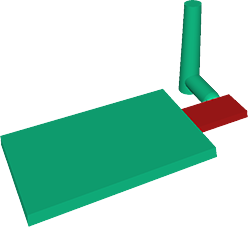

Dimensions:
The typical minimum tab width (W) is 5 mm. The typical minimum tab thickness (H) is 75 percent of the depth of the cavity.