The Warpage indicator, orientation effects result highlights those areas of the part where the out-of-plane deflections attributable to these orientation effects are approaching or exceeding the specified nominal maximum deflection (NMD) value.
One of the three contributors to warpage is variations in the magnitude of shrinkage in the directions parallel and perpendicular to the material orientation direction.
Using this result
The colors displayed in this plot are based on the following assessment criteria.
| Color (Assessment) | Explanation |
|---|---|
| Green (Low) | The out-of-plane deflections are less than 80 percent of the specified NMD value. The contribution of orientation effects to the warpage is low. |
| Yellow (Medium) | The out-of-plane deflections are between 80 percent and 120 percent of the specified NMD. The contribution of orientation effects to the warpage is significant. You should consider taking measures to reduce orientation in this area. |
| Red (High) | The out-of-plane deflections are greater than 120 percent of the specified NMD. Orientation effects are a key contributor to the warpage and corrective measures need to be taken. |
Things to look for
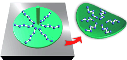
Orientation is caused by the combined effects of material shearing and freezing. As shown in the following diagram, this type of shrinkage produces warpage that is similar to that caused by differential shrinkage.

The following diagram (a) shows the warpage that occurs when parallel shrinkage is greater than perpendicular shrinkage. The following diagram (b) shows the warpage that occurs when the perpendicular shrinkage is higher than parallel shrinkage, which is called doming.


- Changing molding conditions
- Changing gate locations
- Changing part thicknesses
- Changing molding conditions
-
It may be possible to reduce orientation by changing the molding conditions, such as mold temperature, melt temperature, and injection speed. This is the least expensive remedy because it does not require changing the part or the mold.
If you decide to change the molding conditions, you must repeat all the Cooling Quality, Fill, Fill+Pack, and Warp analyses.
- Changing gate locations
-
If changing the molding conditions does not reduce orientation effects sufficiently, you can change the gate type or gate location, or alter the part thickness. Other changes to the gate, such as using an end gating, a fan gate, or multiple gates, can also be tried. Assuming the mold has not already been cut, these remedies will not alter the geometry of simple parts significantly. Changing a gate location will not alter the design specifications of the part and may be an easier remedy for parts with complex geometry and thickness variations. Make the required changes and then re-analyze the part. This can be an iterative process, until the orientation level is acceptable.
- Changing part thicknesses
-
If you decide that changes to the wall thickness will reduce orientation effects for the part, you can alter the wall thickness and re-analyze the modified part model. This can be an iterative process until the differential shrinkage level is acceptable.