The choice of the most appropriate analysis technology depends on the part geometry. Thin shell like parts should use Dual Domain while locally thick parts are best analysed using 3D analysis technology.
The thickness is the smallest dimension of the cross section. To be a shell-like feature, the thickness should be no larger than 4 times a larger dimension of the cross-section, for instance the width. Dual Domain models are best applied when the part has mostly shell-like features. 3D models accurately represent parts where the thickness is not clearly defined.
Therefore, the thickness calculation differs depending on the analysis type being used. For this reason, thickness results will be different whether they are calculated on a Dual Domain or a 3D model.
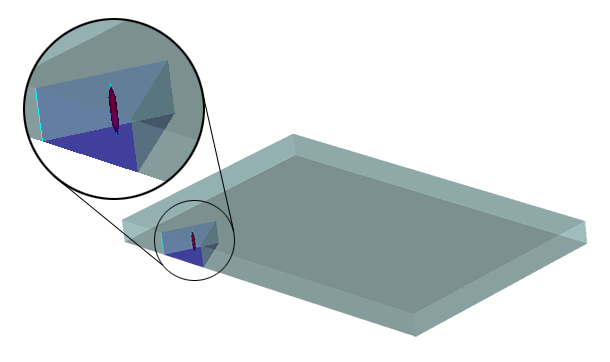
For Dual domain parts, thickness corresponds to the distance between 2 sides of the part. Therefore, the thickness is uniform in shell-like parts with a constant wall thickness. A Dual domain model is best for representing shell-like parts. (see figure 1)

Thickness calculation on a Dual Domain model
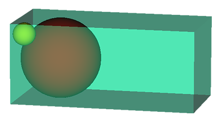
For 3D parts however, the thickness is not obvious and is difficult to visually determine. To calculate thickness variations in a 3D part, the maximal ball algorithm is used.
The maximal ball algorithm considers that a ball rolling inside a part would need to get smaller in order to reach edges (see figure 2). The larger red ball is touching the top and bottom faces of the part, and nearly touching the sides. The smaller yellow ball is touching the top and one side wall, representing the smaller distance as the ball approaches a corner. The thickness is shown as a smaller value in the corner as calculated by the smaller ball. If a 3D model was used for a shell-like part with a "uniform" wall thickness, the 3D model would show the corners of the part to be thinner. The maximal ball technique shows the 3D nature of corners.

Thickness calculation on a 3D model
This method is best for 3D parts as it shows more realistic results. Thin areas of the part will take less time to cool and will have a higher flow resistance. Thicker areas of the part will take longer to cool and will have a lower flow resistance.